
Upflow reactor system with layered catalyst bed for hydrotreating heavy feedstocks

A catalyst layer and heavy raw material technology, applied in the field of reactor systems, can solve the problems of high investment at the high pressure port, increased total investment, and complicated operation

Inactive Publication Date: 2007-05-16
CHEVROU USA INC
View PDF13 Cites 24 Cited by
  • Summary
  • Abstract
  • Description
  • Claims
  • Application Information

AI Technical Summary

Problems solved by technology

Because of the high investment in the high-pressure port in the reactor, the total investment of such a system is greatly increased
Moreover, the operation of such a system is complex and tedious compared to other processes

Method used


Image

  • Upflow reactor system with layered catalyst bed for hydrotreating heavy feedstocks
  • Upflow reactor system with layered catalyst bed for hydrotreating heavy feedstocks
  • Upflow reactor system with layered catalyst bed for hydrotreating heavy feedstocks

Examples


Embodiment Construction

[0026] The present invention can be easily understood with reference to these drawings.

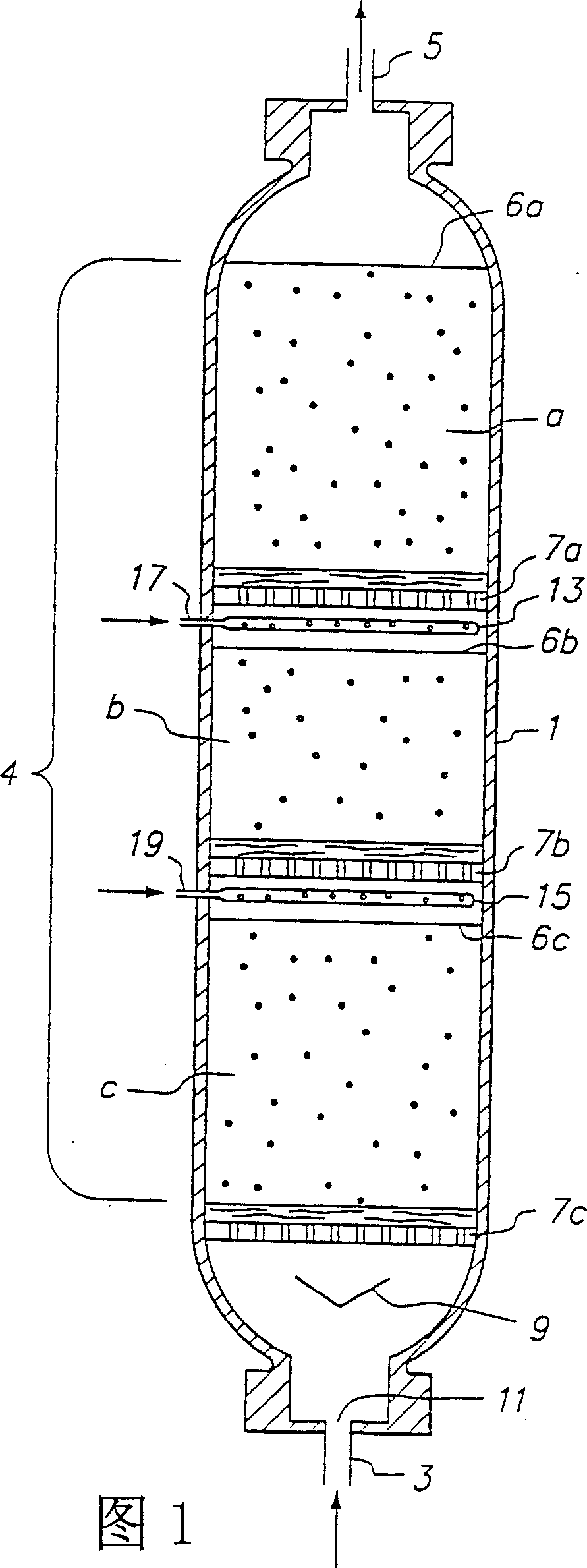
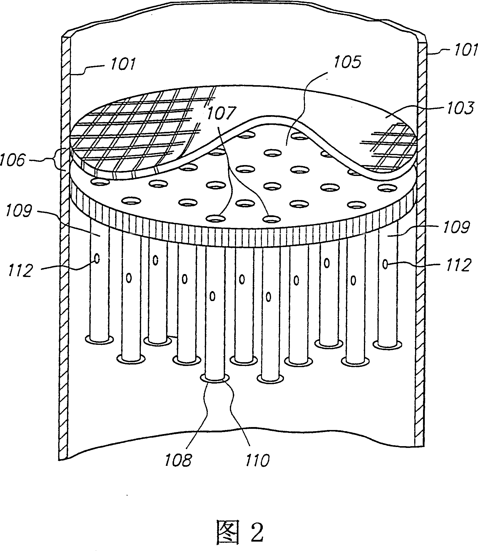
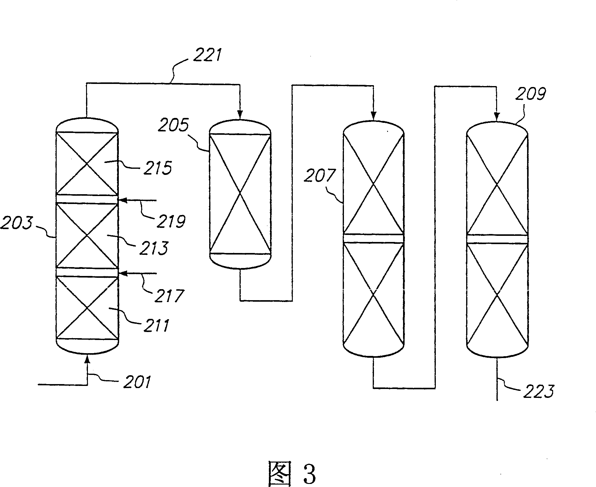
[0027] Figure 1 is a cross-sectional view of one embodiment of the present invention. Hydroprocessing reactor 1 has an inlet conduit 3 for feeding a mixture of heavy feedstock and hydrogen and an outlet conduit 5 for withdrawing a treated product stream along with any excess hydrogen and quench gas or liquid. As shown in this particular embodiment, the catalyst bed 4 is divided into 3 discrete catalyst layers, labeled a, b and c respectively; however, those skilled in the art will appreciate that the number of catalyst layers may be less Up to 2 or more to the number actually required to implement the object of the present invention. In the figures, the top of each discrete catalyst layer is labeled 6a, 6b and 6c, respectively. Each catalyst layer is placed on catalyst support and fluid distribution equipment, for 3 catalyst beds, they are respectively indicated as 7a, 7b and 7c. In th...


PUM


Abstract

A reactor system and process for hydrotreating a heavy feedstock contaminated with metals sulfur and carbon residue using an upflow fixed bed reactor with at least two catalyst layers having different hydrogenation activity.

Description

technical field [0001] The present invention relates to a reactor system and process for the hydroprocessing of heavy feedstocks, especially residues, to reduce the amount of contaminants, especially metals, carbonaceous residues and sulfur. The upflow fixed bed reactor has a layered catalyst bed, in which the catalysts in different layers have different hydrogenation activities, which are used to selectively remove pollutants passing through the entire catalyst bed to prevent clogging and improve catalyst efficiency. life. Background technique [0002] Hydrotreating is a familiar process used to remove contaminants and upgrade heavy feedstocks prior to other processing. The term "hydroprocessing" as used in the present invention means a process for the removal of pollutants, especially metals, carbonaceous residues, nitrogen and sulfur, from heavy feedstocks at superatmospheric pressure and elevated temperature in the presence of hydrogen and a catalyst. As used herein, t...

Claims


Application Information

Patent Timeline
Patent Type & Authority Patents(China)
IPC IPC(8): C10G65/04C10G49/00B01J8/04C10G45/04
CPCB01J2208/025B01J8/0492B01J8/0453C10G65/04C10G49/002
Inventor B·E·里昂纳多F·W·拉姆J·查布特F·J·安特扎拿R·巴啻特尔K·R·基布森R·瑟勒克尔P·C·勒温格
Owner CHEVROU USA INC
Learn More