Friction clutch with intermediate plate mounting system

一种摩擦离合器、中间板的技术,应用在摩擦离合器、离合器、机械驱动离合器等方向,能够解决连接传动带断裂、结构复杂、制造成本提高等问题,达到便于修理和更换、防止损坏、减少制造步骤的效果

Inactive Publication Date: 2007-05-02
EATON CORP
View PDF5 Cites 0 Cited by
  • Summary
  • Abstract
  • Description
  • Claims
  • Application Information

AI Technical Summary

Problems solved by technology

Another disadvantage is that the mechanism must be mounted on the middle plate with the hole or notch in the middle plate and a separate fastener, so the known clutch assembly is complicated in structure and increases in manufacturing cost.
There is also a disadvantage that to protect the drive belt from damage against direct abutment of the spacer and to more precisely control the movement of the compression plate relative to the middle plate, the spacer must directly abut / engage the bar
Another disadvantage is that the maximum axial movement of the intermediate plate is generally not controlled, so that the attached drive belt can be overstretched and break

Method used


Image

  • Friction clutch with intermediate plate mounting system
  • Friction clutch with intermediate plate mounting system
  • Friction clutch with intermediate plate mounting system

Examples


Embodiment Construction

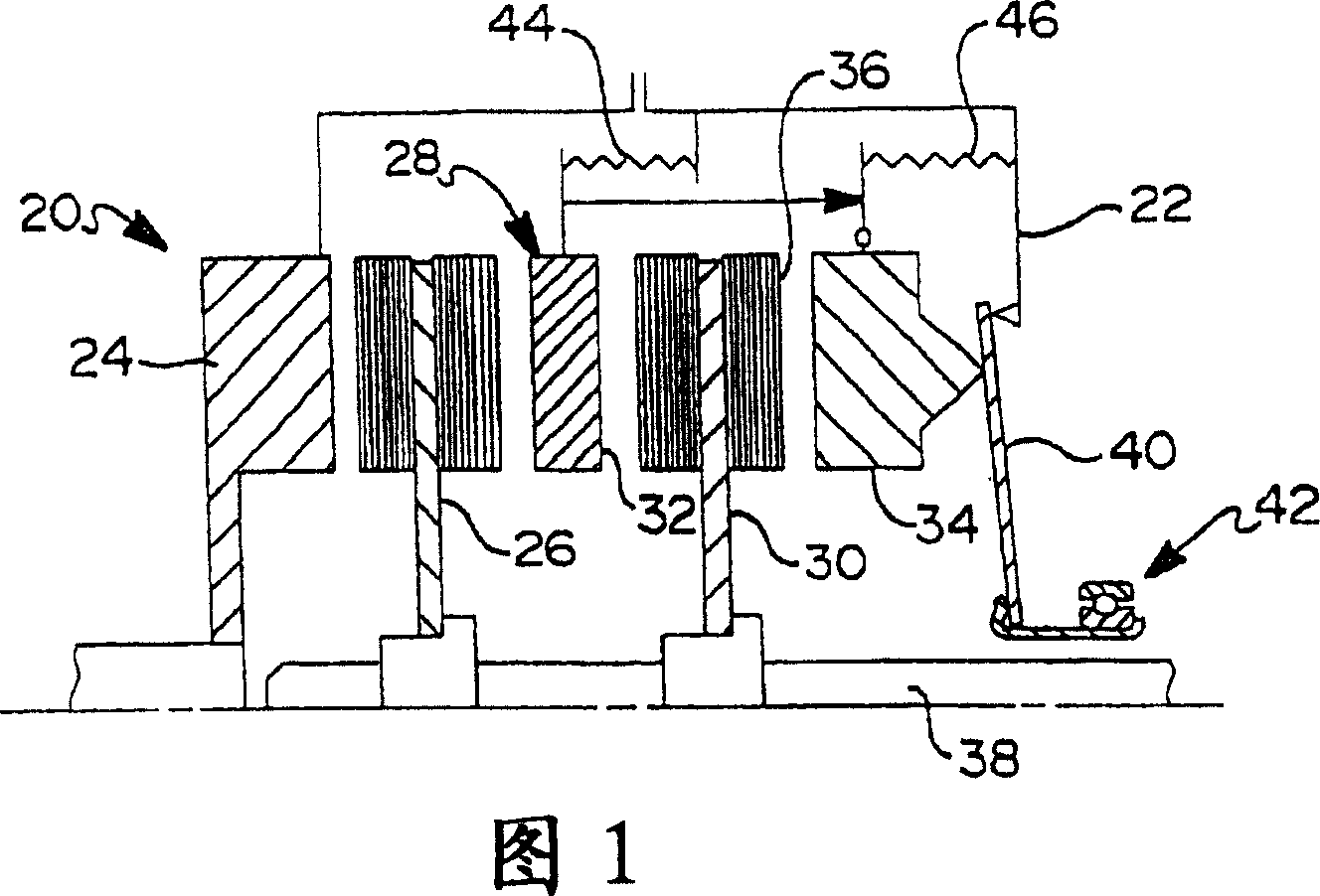
[0021] The accompanying drawings show in detail various preferred embodiments of the invention. FIG. 1 is a schematic diagram of a double-disc friction clutch 20 , and FIG. 2 is a partial cross-sectional view of the clutch 20 . Clutch 20 includes a cover 22 removably mounted on a flywheel 24 of an internal combustion engine (not shown). Cover 22 houses a first friction disc 26 adjacent to flywheel 24 and an intermediate plate 28 adjacent to first friction disc 26 . A second friction disc 30 is adjacent to the transmission-facing side 32 of the intermediate plate 28 and a pressure plate 34 is adjacent to the transmission-facing side 36 of the second friction disc 30 . The first and second friction plates 26, 30 are fixed for rotation on a transmission input shaft 38, but are axially movable relative to each other.

[0022] The middle plate 28 and the pressure plate 34 are fixed to be rotatable together with the cover 22 and relatively movable in the axial direction like the f...


PUM


Abstract

A friction clutch (20), comprising a clutch cover (22), an intermediate plate (28) spaced apart from an engine flywheel (24), a The first friction plate (26), a pressure plate (34) spaced apart from the middle plate (28), and a second friction plate (34) between the middle plate (28) and the pressure plate (34) Disc (30). The clutch (20) further includes a first transmission belt (44) acting on a load on the middle plate (28), a second transmission belt (46) acting on a load on the pressing plate (34) and a belt mounted on the middle plate (28). A spacer arm (79) on (28). The isolation arm (79) abuts against the second drive belt (46) so that the axial movement of the intermediate plate (28) relative to the clutch cover (22) is part of the corresponding axial movement of the pressure plate (34) when the clutch is engaged and disengaged .

Description

technical field [0001] The present invention generally relates to a multi-disc friction clutch, in particular to a multi-disk friction clutch capable of improving the engagement and wear uniformity of the friction discs. Background technique [0002] Friction clutches for transferring torque between a motor vehicle engine and a transmission are well known. A known friction clutch includes two friction plates mounted for rotation about a common axis, a pressure plate / plate, an intermediate plate / plate and a clutch cover. The two friction discs, the pressure plate and the middle plate can move axially relative to each other, so that the pressure plate can move relative to the cover to make the two friction discs and the interposed middle plate axially press against an engine flywheel. A series of drive straps, each comprising one or more elastic members laminated into a leaf spring, are distributed over the periphery of the intermediate and pressure plates to exert a biasing ...

Claims


Application Information

Patent Timeline
Patent Type & Authority Patents(China)
IPC IPC(8): F16D13/71F16D13/50F16D13/38F16D13/69
CPCF16D13/71F16D13/505F16D2013/706F16D13/385
Inventor D·V·戈什努尔S·M·彼得森K·F·施洛瑟
Owner EATON CORP
Why Eureka
Try Eureka