Cable fixer

A cable fixing device and cable technology, applied in the direction of the cable suspension device, etc., can solve the problems of transmission line paralysis, poor contact of cable joints, complete separation, etc., to eliminate displacement, facilitate installation and disassembly operations, and ensure connection quality effect

Inactive Publication Date: 2007-04-11
上海国润通信技术有限公司
View PDF5 Cites 0 Cited by
  • Summary
  • Abstract
  • Description
  • Claims
  • Application Information

AI Technical Summary

Problems solved by technology

Large longitudinal loads and stresses may lead to poor contact or complete separation of cable joints, causing paralysis of the entire transmission line

Method used


Image

  • Cable fixer
  • Cable fixer
  • Cable fixer

Examples


Embodiment Construction

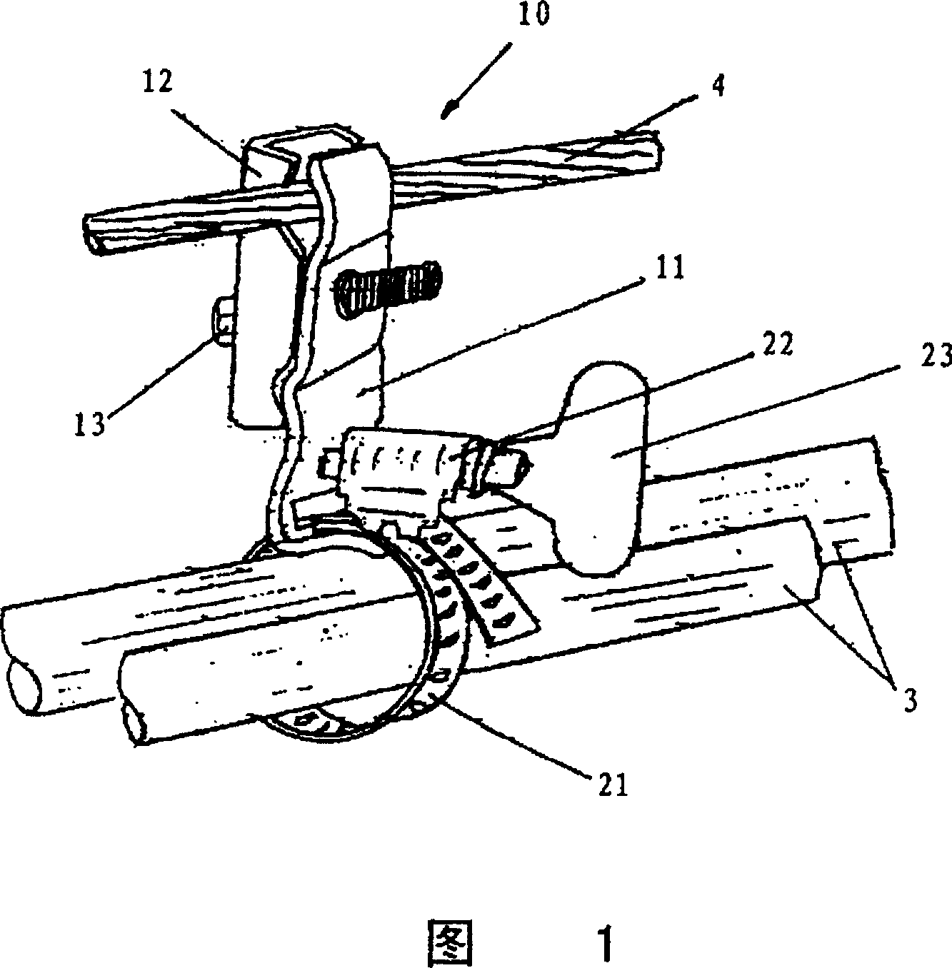
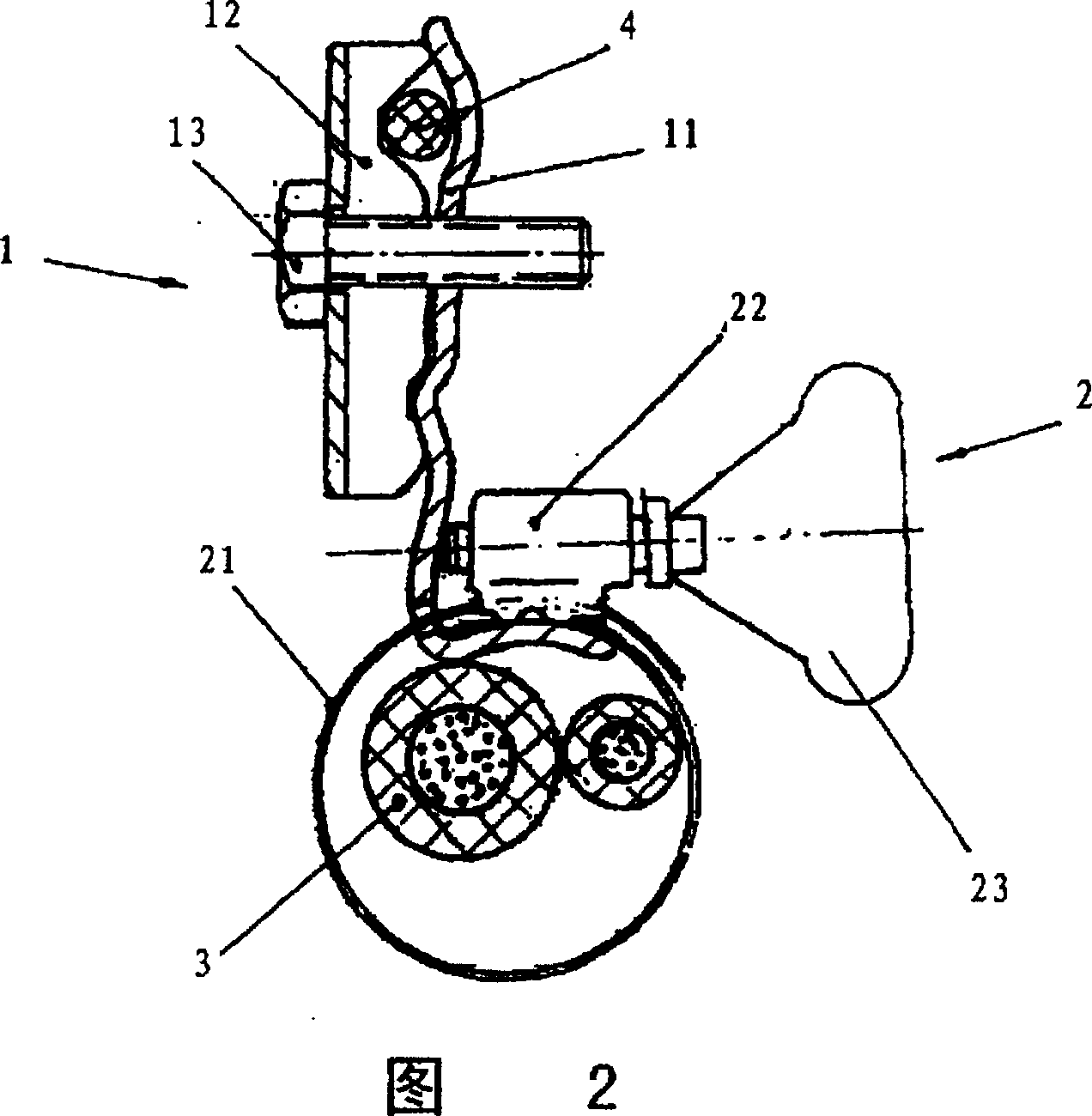
[0022] Referring to the accompanying drawings, the cable fixing device 10 generally includes a fixing mechanism 1 fixedly connected to the supporting steel cable 4 and a cable clamping mechanism 2 clamping the transmission cable 3 .

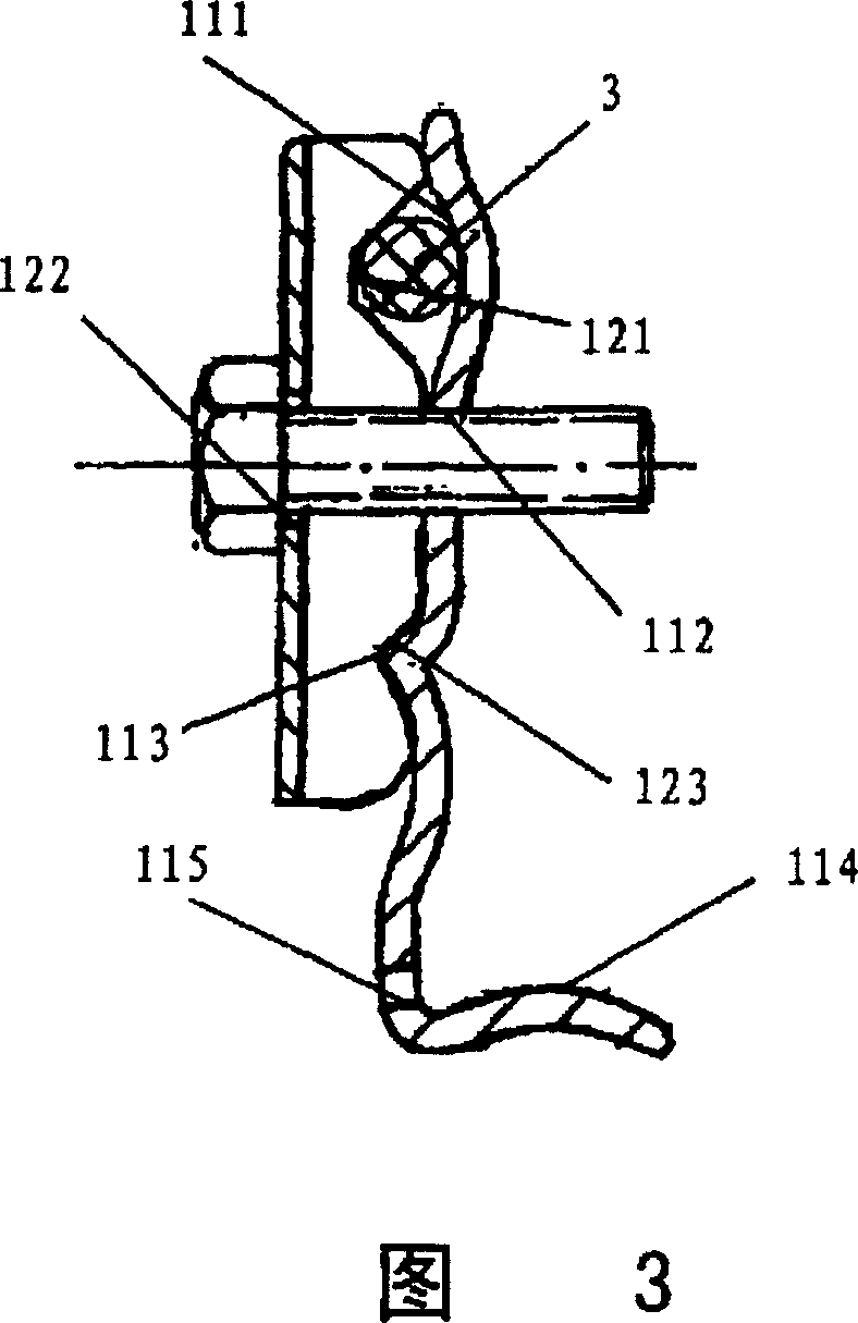
[0023] The fixing mechanism 1 is joined together by a supporting part 11 and a locking part 12 through a fastening bolt 13 . The support member 11 is a stainless steel sheet roughly bent into an L shape, and an arc-shaped groove 111 for accommodating the support cable 4, a bolt hole 112 below the holding groove 111, and a bolt hole located at the bottom of the bolt hole are formed on its long side. The rib 113 below 112 and the groove 111 extend substantially parallel to the rib 113 . The short side of the L-shaped support member 11 forms an upwardly curved arc-shaped support surface 114 for supporting a tightening band (described below) wound in a loop. The L-shaped support 11 is formed with a notch 115 approximately at its corner, for the tigh...


PUM


Abstract

This invention provides a cable fixing device containing a fixing unit suitable for fixedly connecting with a supporting steel cable and a clamping device which clamps at least one cable and the fixing unit connected with the cable clamping device. The cable clamping device uses a screw arbor type tension regulator beneficial to realizing convenient and realiable clamping of cable and capable of transferring environmental loads like wind, snow, etc. and its own gravity to the high-strength supporting steel cable especially eliminating the displacement of transmission lines in the longitudinal direction due to temp. effect and securing long-time reliable work of cables and line route.

Description

technical field [0001] The present invention relates to a cable fixing device, in particular to a fixing device for fixing transmission cables such as optical cables and electric cables to supporting steel cables. Background technique [0002] Transmission cables such as optical cables and electric cables sometimes need to be laid overhead. Since such transmission cables themselves are not rigid enough to support themselves, additional supporting devices need to be provided to keep the cables in position in the air. Typically, a stronger supporting cable is provided coextensively parallel to the transmission cable and the cables are fixed to the supporting cable at intervals so that the entire cable is suspended from the supporting cable. A traditional method of fixing the transmission cable to the supporting steel cable is to suspend the cable from the steel cable with a hanging device such as a shackle, that is, to hang and connect the transmission cable with a shackle at ...

Claims


Application Information

Patent Timeline
Patent Type & Authority Patents(China)
IPC IPC(8): H02G7/08
Inventor 陆来平张玉藩
Owner 上海国润通信技术有限公司
Why Eureka
Try Eureka