
Warp knitting machine with at least one stripping comb

A technology of warp knitting machine and floral bar, which is applied in the field of warp knitting machine, can solve problems such as the deformation of the second yarn guide rod, and achieve the effect of increasing life and improving sliding performance

Inactive Publication Date: 2007-03-14
KARL MAYER CHINA
View PDF11 Cites 3 Cited by
  • Summary
  • Abstract
  • Description
  • Claims
  • Application Information

AI Technical Summary

Problems solved by technology

If this end abuts against the stop, the second yarn guide rod of the yarn feeder may be deformed

Method used


Image

  • Warp knitting machine with at least one stripping comb
  • Warp knitting machine with at least one stripping comb
  • Warp knitting machine with at least one stripping comb

Examples


Embodiment Construction

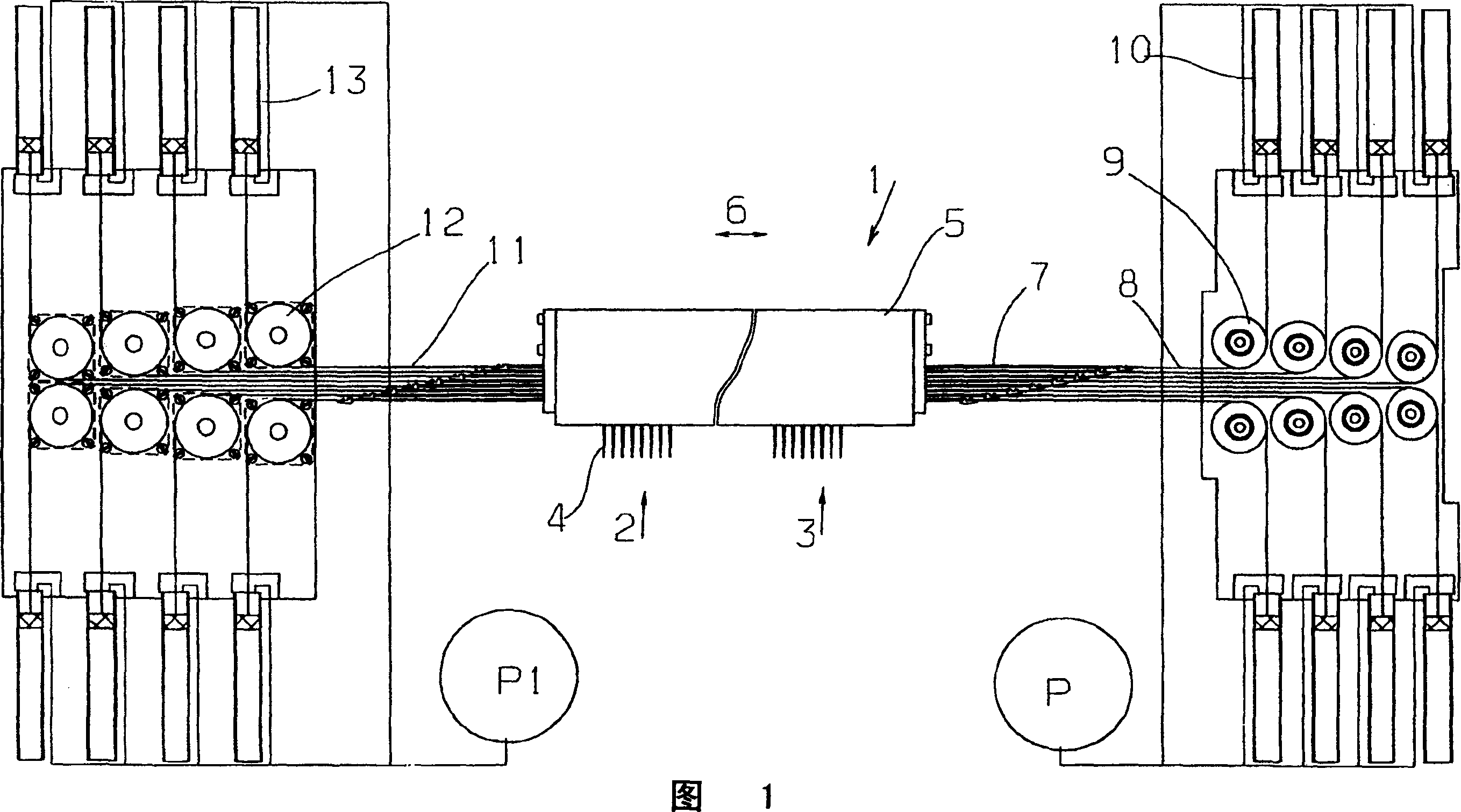
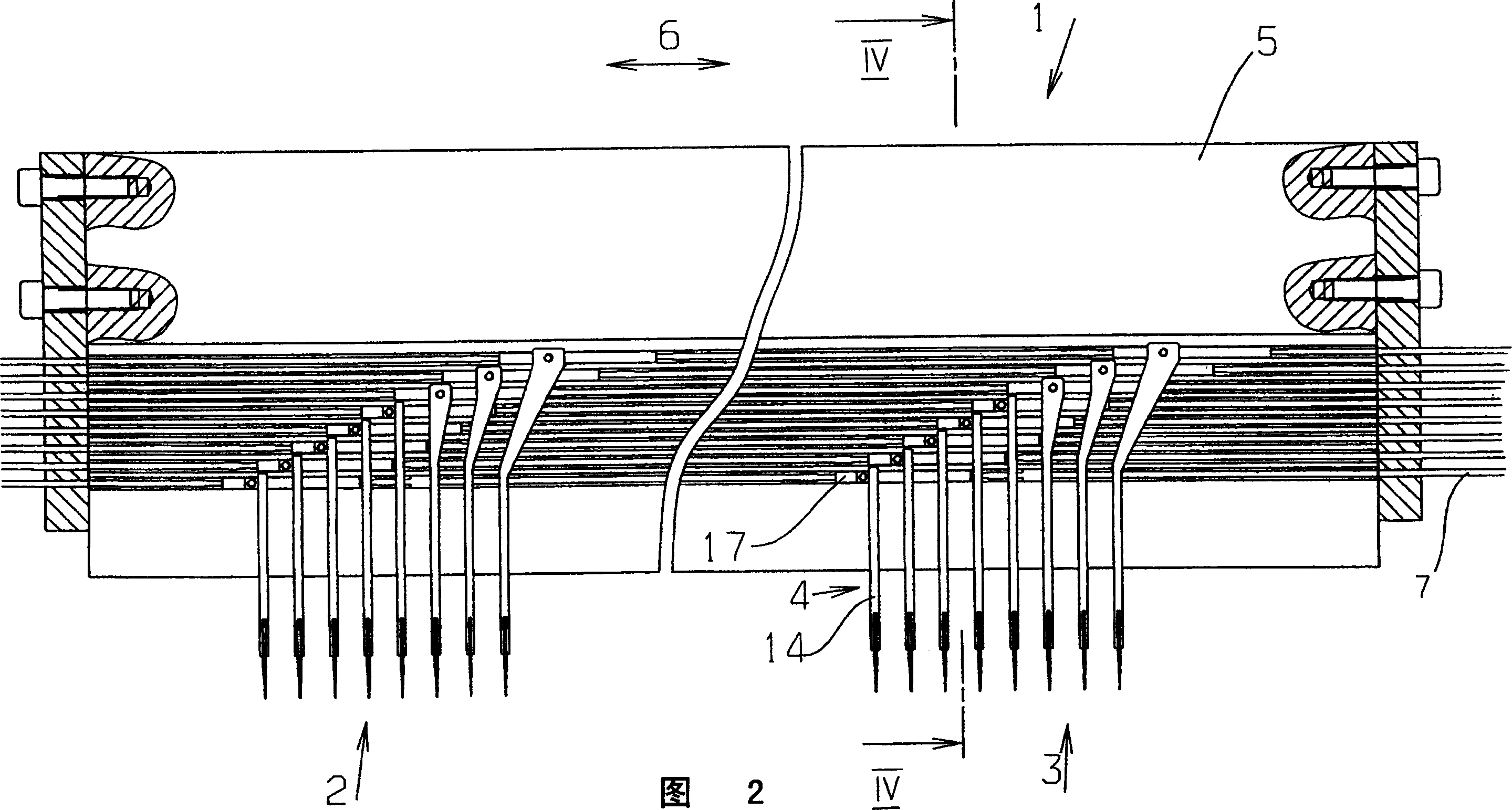
[0034] Fig. 1 shows a flower bar 1 with multiple sets of 2,3 yarn guides 4. The thread guides 4 of each group 2, 3 that are mutually consistent, that is, the first, second, third, etc. thread guides 4 of each group 2, 3 are collectively driven, that is to say, they are relative to the bar holder The frame 5 is movable in a traversing direction 6 indicated by a double arrow, a device (not shown in detail) is provided, by means of which the bar carriage 5 is also movable in the traversing direction 6 .

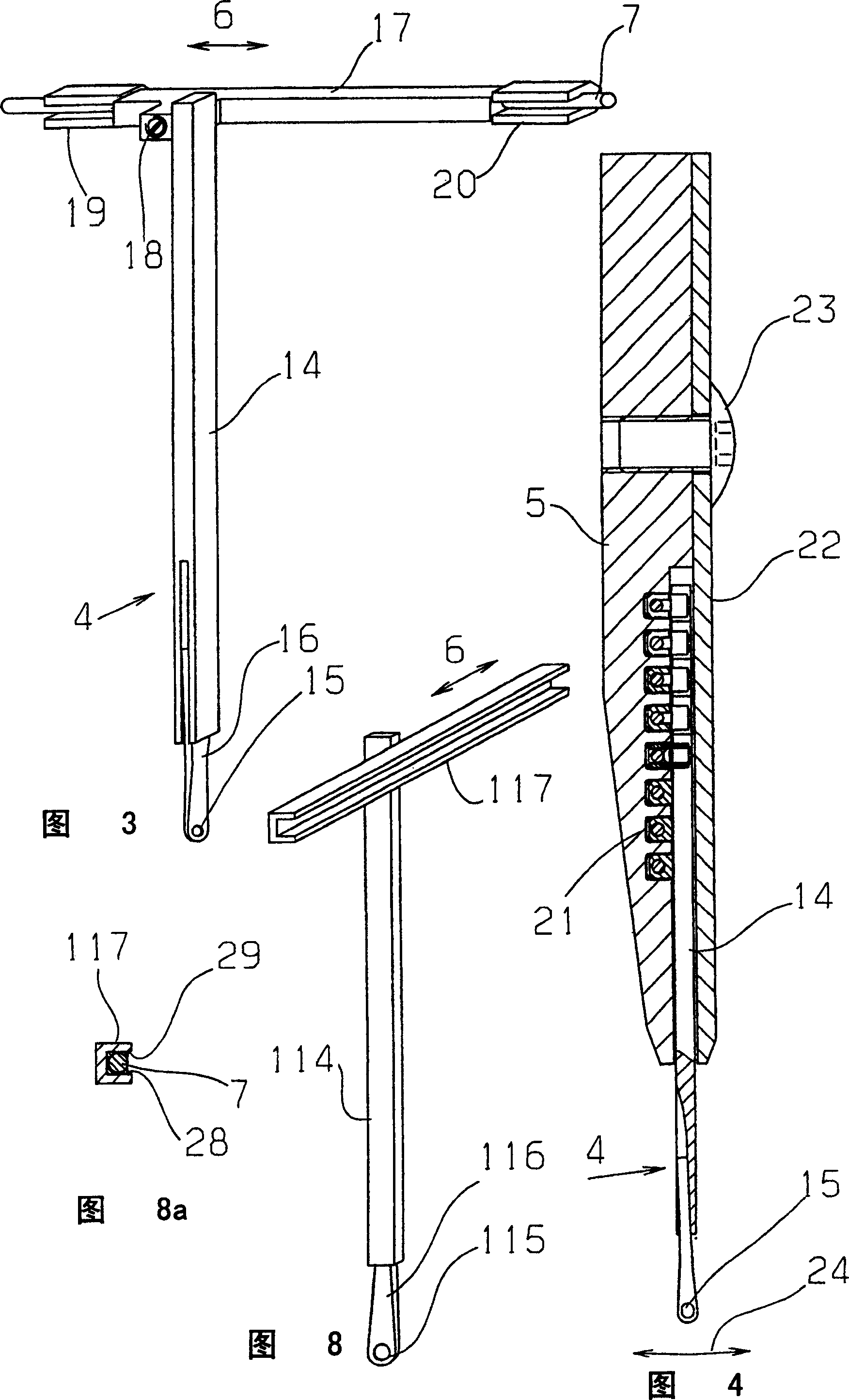
[0035] For driving the thread guide 4, traction elements 7 are provided, which are of wire or cable construction and therefore have a small cross-section. The traction elements 7 , which will be described in more detail below with reference to FIGS. 2 and 4 , are arranged one above the other perpendicular to the traversing direction. Each traction element 7 is connected to a drive motor 9 via a drive belt 8, wherein the drive belt 8 is fixed at its other end in a tension member...


PUM


Abstract

The warp knitting machine is comprise of: the pattern guide bar(1) containing the yarn guides (4) reciprocated by a driving device; the yarn guides(4) containing the holders(17) extended in the shift direction(6); and the holders(17) connected vertically with the shafts(14) and fixed on the cords(7).

Description

technical field [0001] The invention relates to a warp knitting machine having at least one patterned bar with a plurality of thread guides which can be moved back and forth in the direction of traverse by a drive which acts on the thread guides via a traction element. Background technique [0002] DE4114012C2 discloses such a warp knitting machine, wherein the yarn guide is connected to the driving motor through a traction rope. The yarn guide is hingedly suspended on a bar support. Thus, the motion of the pulling rope is converted into an oscillating motion of the yarn guide. A stop that limits the swing angle of the end of the yarn guide on which a yarn guide eye is provided is also provided. If this end abuts against the stop, the second yarn guide rod of the yarn guide may be deformed. [0003] DE2436452B1 has pointed out a kind of warp knitting machine with weft insertion device, and in this warp knitting machine, the yarn guide of tube needle structure is fixed in ...

Claims


Application Information

Patent Timeline
Patent Type & Authority Patents(China)
IPC IPC(8): D04B27/26D04B27/32
CPCD04B27/32D04B27/26
Inventor K·米斯塔
Owner KARL MAYER CHINA
Learn More