
Electronic camera device

A camera device, electronic technology, applied in television, electrical components, image communication, etc., can solve the problem of not revealing dust and so on

Inactive Publication Date: 2007-03-07
OLYMPUS OPTICAL CO LTD
View PDF4 Cites 0 Cited by
  • Summary
  • Abstract
  • Description
  • Claims
  • Application Information

AI Technical Summary

Problems solved by technology

[0004] However, the above-mentioned Japanese Patent Application No. 2000-401291 does not disclose the point of removing the dust attached to the glass plate when attaching and detaching the accessory device.

Method used


Image

  • Electronic camera device
  • Electronic camera device
  • Electronic camera device

Examples


Embodiment Construction

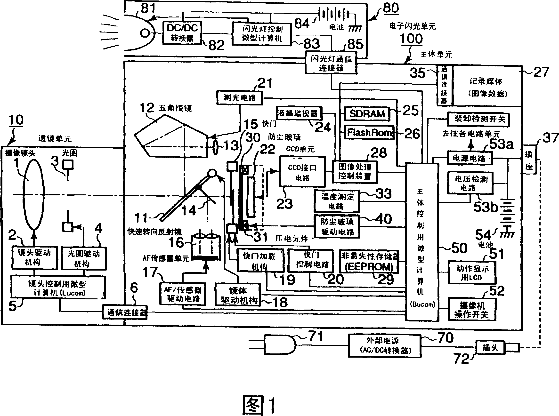
[0027] Hereinafter, an electronic imaging device with a dust-proof function according to the present invention will be described in detail based on an embodiment of a camera system including an imaging element and various accessory devices.

[0028] FIG. 1 is a block diagram showing the configuration of a camera system according to an embodiment of the present invention. This camera system is mainly composed of a main body unit 100 as a camera body and as an accessory device such as: a lens unit 10 as an interchangeable lens, a recording medium 27 for recording captured image data, an external power supply 70, and an externally installed electronic flash unit 80. And so on.

[0029] The lens unit 10 desired by the user is detachably set by a lens holder (not shown) provided on the front surface of the main body unit 100 .

[0030] The above-mentioned recording medium 27 is an external recording medium such as various memory cards or an externally mounted HDD, and can communic...


PUM


Abstract

The present invention provides an electronic imaging device with a dust-proof function of securely removing dust sticking on a constitution member when an accessory unit is attached and detached. The electronic imaging device is a device (camera) where an accessory such as a recording medium 27, an external power source 70 or an electronic flash unit 80 can be attached and detached, and comprises a photographic lens 1 which forms an optical image of a subject, a CCD unit 22, a constitution member (dust-proof glass 30) arranged between the CCD and the photographic lens, and a dust removing means (a piezoelectric element 31 and a dust-proof glass driving circuit 40) which removes stuck dust by vibrating the glass at a plurality of kinds of frequencies and efficiently performs the dust removing operation through the resonating operation of a piezoelectric element 31 in effective timing corresponding to the attachment of one of the accessories.

Description

technical field [0001] The present invention relates to an electronic imaging device having an imaging element, and to an electronic imaging device with a dustproof function capable of removing dust adhering to components such as a camera system. Background technique [0002] Conventionally, as an example of technology related to the dust-proof function of an optical device, it has been proposed to remove dust adhering to the glass by vibrating a cover glass (dust-proof glass) that protects an imaging element. Specifically, there is, for example, the proposal described in Japanese Patent Application No. Hei 2000-401291, in which a piezoelectric element is used as a device for vibrating a glass plate. The piezoelectric element expands and contracts in response to an applied voltage, and vibrates the mounted glass plate at a predetermined cycle. [0003] Various attachments are freely attached and detachable, and the desired attachments are attached to the main body for use. ...

Claims


Application Information

Patent Timeline
Patent Type & Authority Patents(China)
IPC IPC(8): H04N5/225G03B17/02G03B17/14
Inventor 伊藤顺一
Owner OLYMPUS OPTICAL CO LTD
Learn More