Spinning machine with many adjacently arranged spinning spindle position

A kind of spinning machine, many advanced technologies, applied in the field of spinning machines with adjacently arranged spinning spindle positions, can solve problems such as failure to combine fibers, affect collection effect, blockage, etc.

Inactive Publication Date: 2007-02-07
MASCHINENFABRIK RIETER AG
View PDF5 Cites 0 Cited by
  • Summary
  • Abstract
  • Description
  • Claims
  • Application Information

AI Technical Summary

Problems solved by technology

With known spinning machines of this type, the suction duct also has the disadvantage that there is no reinforcing plate between the two spinning spindles, the suction duct also extends directly to each front roller due to the extremely small thickness of the metal foil
The disadvantage is that, mainly, the fibers can be collected between each spinning position, but for some reason the fibers are not integrated into the fiber sliver when they are collected
These discrete individual fibers may at some point uncontrollably enter the fiber strip and / or become clogged in the perforations of the breathable conveyor belt, thereby gradually affecting the aggregation effect

Method used


Image

  • Spinning machine with many adjacently arranged spinning spindle position
  • Spinning machine with many adjacently arranged spinning spindle position
  • Spinning machine with many adjacently arranged spinning spindle position

Examples


Embodiment Construction

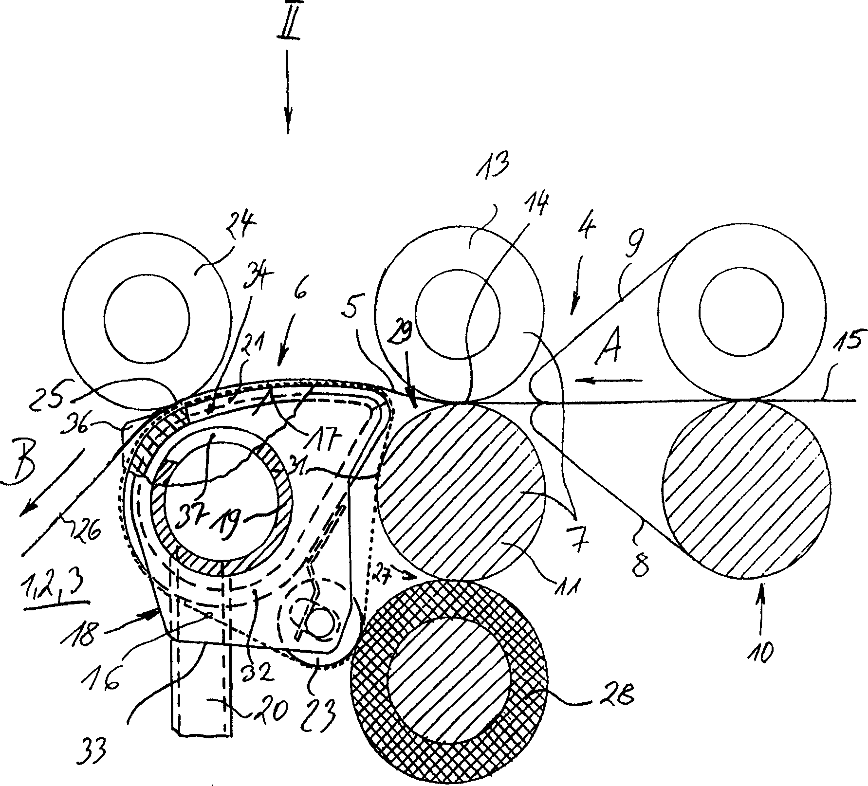
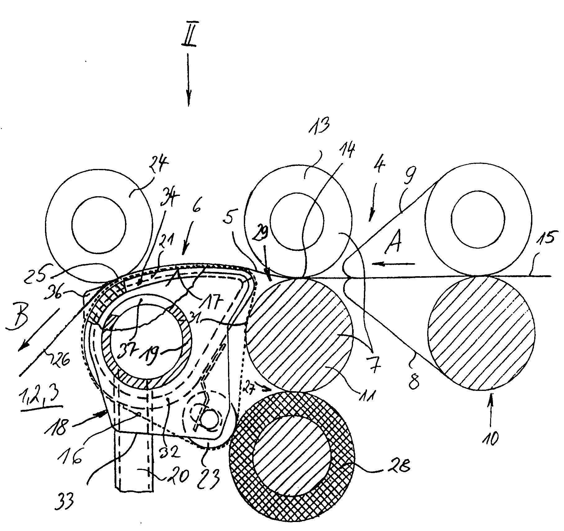
[0014] according to figure 1 The spinning machine shown in the part of Fig. 2 is firstly a ring spinning frame. Usually, this kind of spinning machine has many adjacently arranged spinning positions according to the longitudinal direction of the machine. From Fig. 2, it can be seen that three Spinning positions 1, 2 and 3.

[0015] Each spinning position 1, 2, 3... has a drafting unit 4, but in figure 1 Only its terminal area is drawn in the drawing, and there is a collection area 6 for bundling the drawn but untwisted fiber strip 5, which is located downstream of the drafting device 4. The other components of the spinning positions 1, 2, 3... are not shown.

[0016] Each drafting unit 4 has a pair of front rollers 7, and an apron roller 10 for guiding the lower apron 8 and the upper apron 9 mounted upstream of the pair of front rollers. All the other rollers of the drafting device 4 are not shown on the figure.

[0017] The front roller pair 7 has a driven bottom roller 1...


PUM


Abstract

The invention relates to a spinning frame having plural spinning stations placed adjoiningly, each of the spinning stations comprises a drawing unit having a front roller pair forming a front nip line, and a condensing zone which is placed on the downstream side of the drawing unit and condenses a drawn fiber strand. Each condensing zone has an air-penetrating transfer belt for transferring the fiber strand, and the transfer belt is guided on a slide surface having sucking slits. The sucking slit-having slide surface is installed in a single housing which is placed on a sucking tube extending over the plural spinning stations. The sucking tube is placed at a certain distance from the front roller pair, and this distance is bridged over with the slide surface of each single housing.

Description

technical field [0001] The invention relates to a spinning machine having a plurality of adjacently arranged spinning positions, each spinning position having a drafting device with a pair of front rollers forming a front nip line and a The collection of a drafted fiber sliver collection area, the collection area contains a breathable conveyor belt conveying fiber sliver, the latter is guided by a guide surface with a suction slot, the guide surface of a number of conveyor belts It is installed on a suction pipe extending to many spinning positions and protrudes into the wedge-shaped gap formed by the front roller pair. Background technique [0002] The drawn fiber sliver in the drafting unit of the spinning machine is then given a spinning twist. If this spinning twist is applied directly after drafting, a so-called spinning triangle may form in the front roller pair of the drafting device, which triangle contains edge fibers that are not properly incorporated into the twi...

Claims


Application Information

Patent Timeline
Patent Type & Authority Patents(China)
IPC IPC(8): D01H5/60D01H5/72D01H1/02D01H1/22D01H5/26D01H5/66D01H5/86D01H11/00
CPCD01H1/025D01H5/72D01H5/86D01H1/22D01H5/26
Inventor G·谢夫勒
Owner MASCHINENFABRIK RIETER AG
Why Eureka
Try Eureka