Fluorophor detecting method and fluorophor detecting apparatus

A detection method and detection device technology, applied in measuring devices, photometry, fluorescence/phosphorescence, etc., can solve the problems of uneven illumination, no interference fringes, interference fringes, etc.

Inactive Publication Date: 2006-12-20
KOKUSA ELECTRIC CO LTD
View PDF1 Cites 0 Cited by
  • Summary
  • Abstract
  • Description
  • Claims
  • Application Information

AI Technical Summary

Problems solved by technology

From the image, it can be seen that interference fringes are generated on the entire light emitting surface 42 of the plasma display 41.
[0011] In addition, the ultraviolet illuminating part 34 is arranged on both sides of the glass substrate 31 coated with phosphor, and irradiates ultraviolet rays, so the ultraviolet rays cannot be irradiated on the glass substrate 31 uniformly.
As a result, uneven illumination occurs, which also becomes a cause of misdetection of uneven coating
[0012] In addition, there is a known detection method of a plasma display panel (for example, please refer to Patent Document 1), which uses a color TV camera or a black-and-white TV camera to detect uneven coating of R, G, and B phosphors. However, there is no mention of the above-mentioned interference fringe phenomenon in the method

Method used


Image

  • Fluorophor detecting method and fluorophor detecting apparatus
  • Fluorophor detecting method and fluorophor detecting apparatus
  • Fluorophor detecting method and fluorophor detecting apparatus

Examples


Embodiment Construction

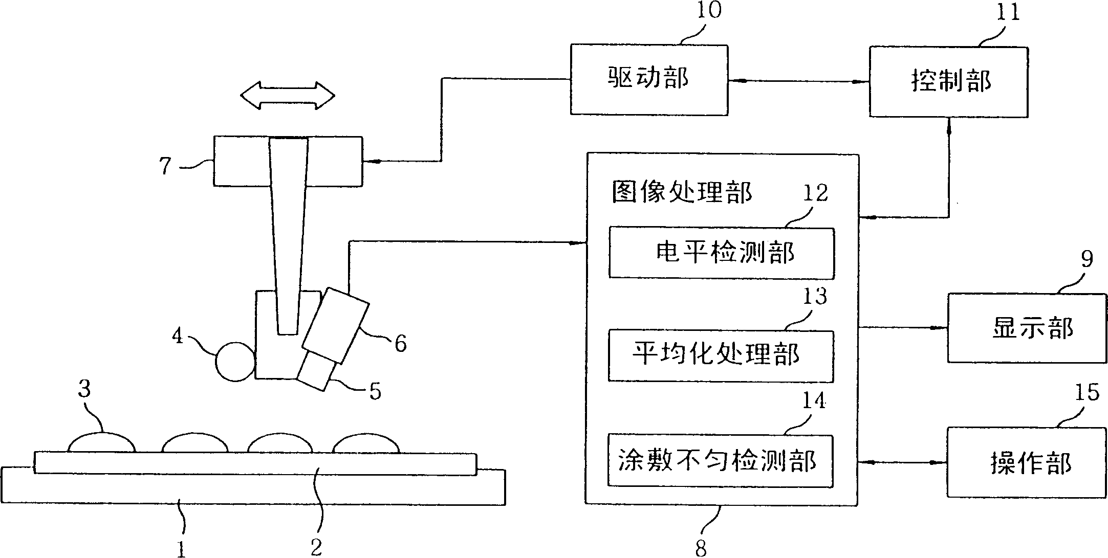
[0035] figure 1 One embodiment of the phosphor detection device of the present invention is shown. figure 1 Among them, 1 denotes a table for placing glass substrates such as plasma displays, 2 denotes glass substrates such as plasma displays, 3 denotes R, G, and B phosphor strips, 4 denotes a light source for ultraviolet illumination that makes phosphor strips 3 emit light, and 5 denotes sequential mounting. An optical system with lenses and R, G, and B color filters, 6 represents an imaging unit such as a line sensor camera for imaging, and 7 indicates a moving mechanism for scanning the upper part of the glass substrate 2 along the substrate 2 with the light source 4 and the imaging unit 6 8 represents an image processing part for detecting uneven coating, 9 represents a display part such as a color monitor for displaying detection results, and may also be composed of a printing part such as a printer, 10 represents a driving part for driving the moving mechanism part 7, ...


PUM


Abstract

In a defect detection of a striped fluorescent material stripe coated on a glass substrate of, e.g. a plasma display, there occurs a problem that a defective coating of the striped fluorescent material cannot be properly detected due to a moire phenomenon incurred by a non-radiating portion of the striped fluorescent material and also by nonuniformity of an ultraviolet illumination being used for exciting the fluorescent material to radiate. A fluorescent detecting method includes the steps of applying an ultraviolet light to a plurality of a striped fluorescent material formed on a substrate; photographing a light radiated from the striped fluorescent material; detecting signal levels of the photographed picture; averaging signal levels of portions, the signal levels of the portions being equal to or greater than a predetermined value; and detecting a defective coating of the striped fluorescent material based on the averaged result.

Description

technical field [0001] The present invention relates to a phosphor detection method and phosphor detection device, in particular to a phosphor detection method and phosphor detection device for detecting coating defects of phosphors coated on glass substrates such as plasma displays. Background technique [0002] A prior art example will be described with reference to FIG. 3 . 3 is a block diagram showing a schematic configuration of a phosphor inspection device for inspecting coating defects of phosphors coated on a glass substrate such as a plasma display. [0003] In Fig. 3, 31 denotes a glass substrate coated with a phosphor, 32 denotes an imaging section composed of a CCD camera, etc., 33 denotes an optical system of the imaging section 32, 34 denotes an ultraviolet illuminating section for making the phosphor emit light, and 35 denotes a detection coating. An image processing unit for uneven defects, 36 denotes a display unit for displaying detection results. In addi...

Claims


Application Information

Patent Timeline
Patent Type & Authority Patents(China)
IPC IPC(8): G01N21/64G01M11/00G01B11/30G01J1/00H01J9/22H01J9/42
CPCH01J9/42
Inventor 渡贯明男
Owner KOKUSA ELECTRIC CO LTD
Why Eureka
Try Eureka