Single tooth, biteeth shaped large angle flexible laminated coupler

A large-angle, coupling technology, applied in elastic couplings, couplings, mechanical equipment, etc., can solve problems such as fretting wear, angle compensation cannot be large, and limit development and application

Inactive Publication Date: 2006-11-29
王陈彬
View PDF0 Cites 0 Cited by
  • Summary
  • Abstract
  • Description
  • Claims
  • Application Information

AI Technical Summary

Problems solved by technology

However, the current design technology of this kind of flexible lamination coupling is relatively complicated, involving issues such as composite laminates, nonlinear large deformation, fretting wear, stability, etc.
Its design has always been a troublesome problem. The biggest weakness is that the angle compensation cannot be large, only about 1°, and the number of holes is smaller, which limits its development and application to a large extent.

Method used


Image

  • Single tooth, biteeth shaped large angle flexible laminated coupler
  • Single tooth, biteeth shaped large angle flexible laminated coupler
  • Single tooth, biteeth shaped large angle flexible laminated coupler

Examples


Embodiment Construction

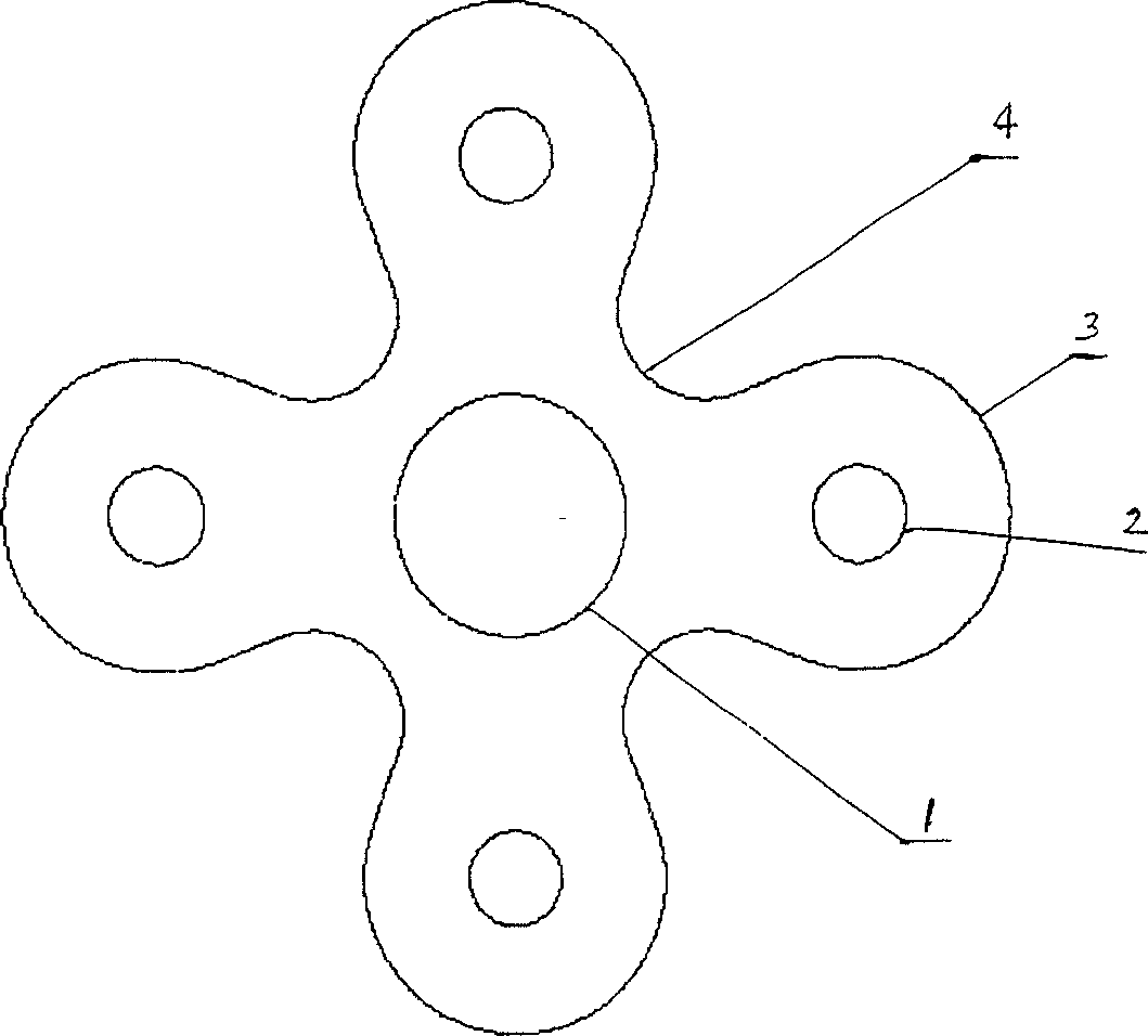
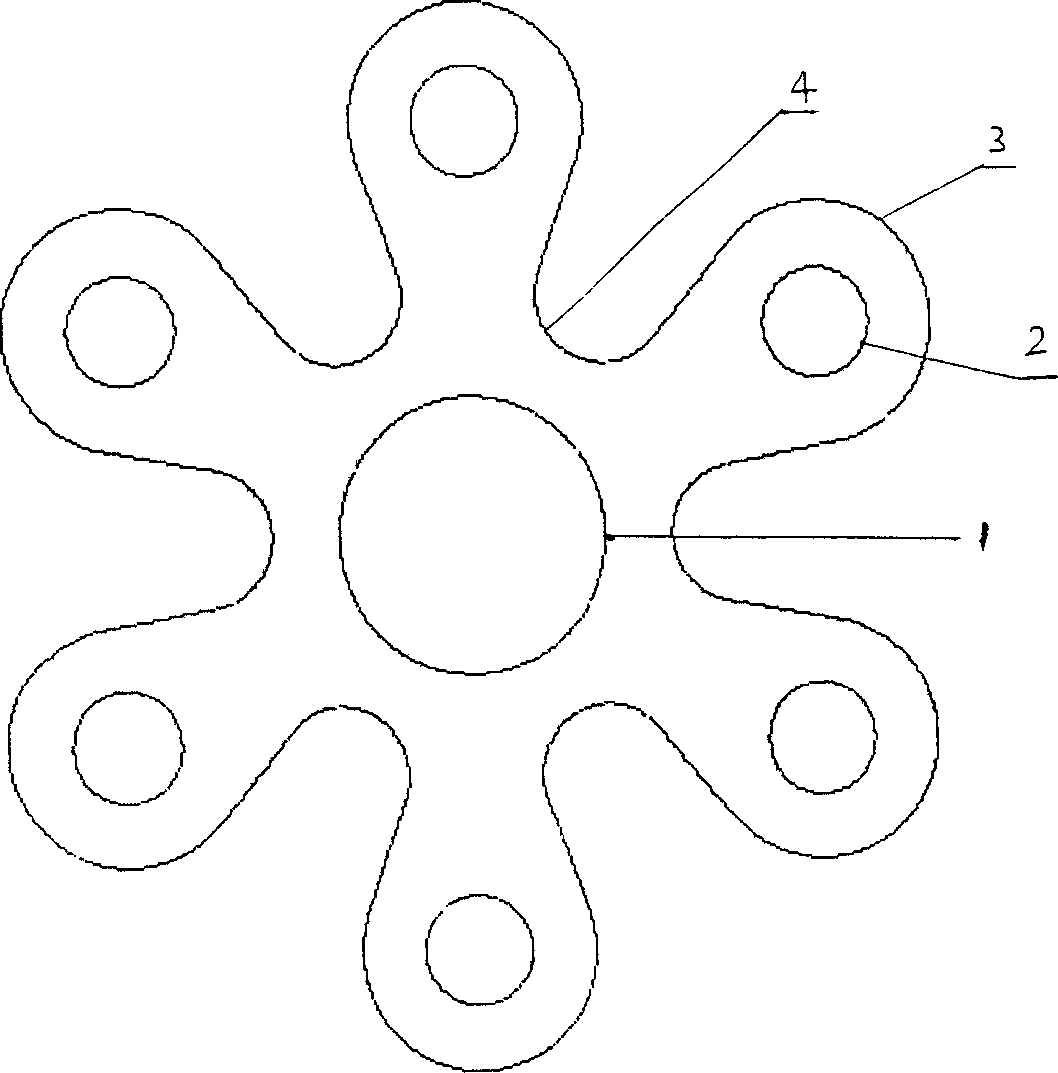
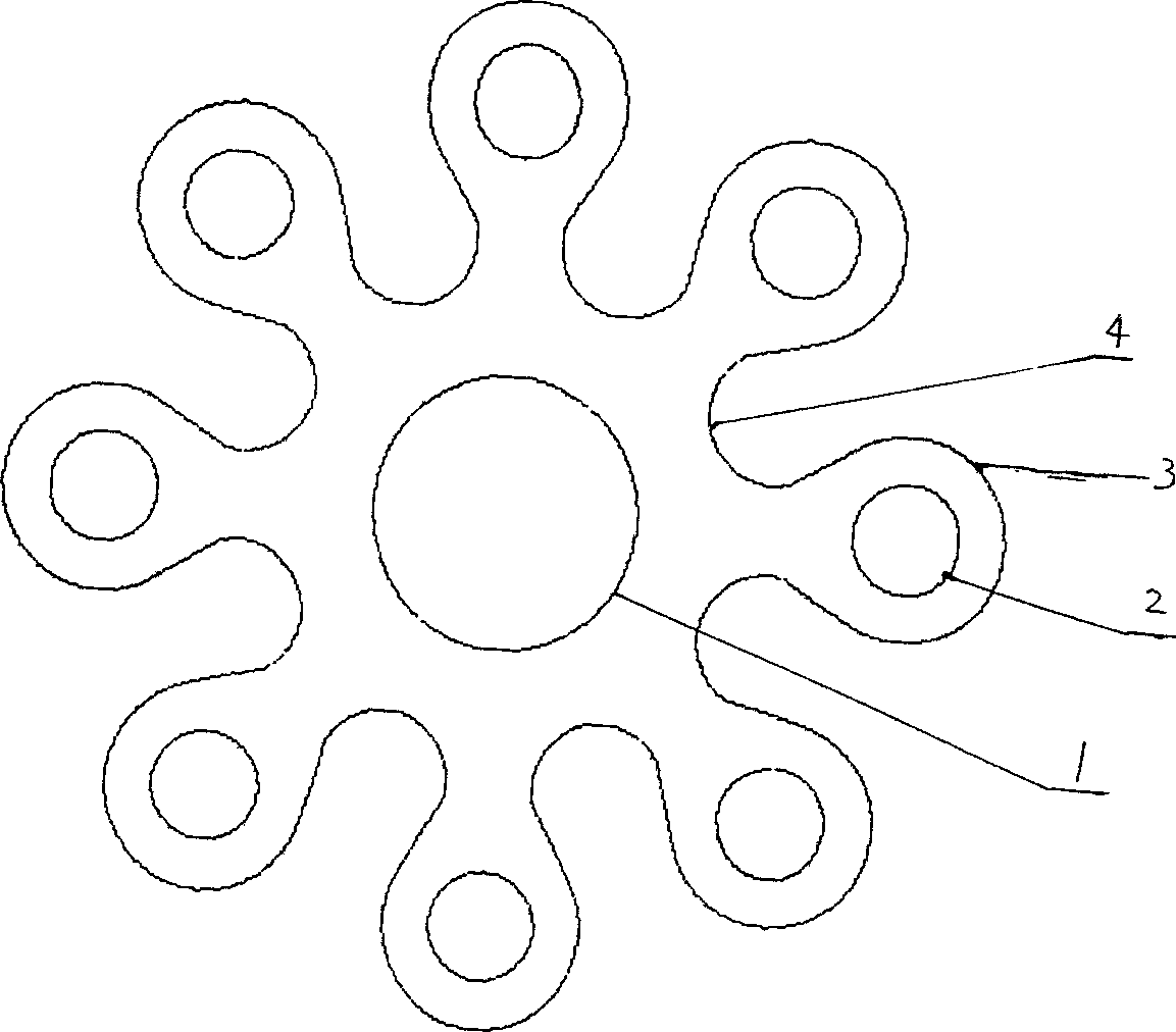
[0023] Figure 1 is a schematic diagram of the planar structure of a single-tooth-shaped large-angle flexible lamination coupling with a single-tooth concave arc. exist There is a bolt hole circle 2 with the same radius on each of the 2n angle bisectors, and there are 2n lamination outer circle arcs 3 with the same radius as the bolt hole circles with the same center as the 2n bolt hole circles respectively. Each of the 2n angle bisectors between two adjacent bolt hole circles 2 has a single-tooth concave arc 4, and the outer circular arc 3 of the lamination is tangent to the single-tooth concave arc by an outer common tangent line. Thus, the distance from the center of the lamination shaft to the center of the single-tooth concave arc is smaller than the distance from the center of the lamination shaft to the center of the bolt hole plus the radius of the outer arc of the lamination. n in 2n is equal to 2, 3, 4, 5, 6 respectively. Therefore, there are 4-hole, 6-hole, 8-hol...


PUM


Abstract

A large-angle flexible laminated single-tooth or dual-tooth shaft coupler is composed of internal central hole for shaft, screw holes, external arcs, and femal arcs for single-tooth one or the male arcs and female arcs for dual-tooth one. Its advantages are large compensating angle, high stability and long service life.

Description

Technical field: [0001] The invention relates to single-tooth and double-tooth large-angle flexible lamination couplings. Background technique: [0002] Since a British company invented the flexible laminated coupling in 1947, it has been developed and widely used in the world for more than 50 years. Now it is industrially developed countries in the world, such as Britain, the United States, France and Germany. , Japan, etc. have been widely used and exported, and have been greatly developed and improved in design technology and manufacturing technology, and are widely used in aviation, ships and other fields. The current flexible lamination coupling can not only play a good connection role, but also has a good compensation effect in the axial direction, angular direction and radial direction. It also has good dynamic characteristics, absorbs vibration, does not need lubrication, has a simple structure and low cost. However, the current design technology of this kind of fl...

Claims


Application Information

Patent Timeline
Patent Type & Authority Patents(China)
IPC IPC(8): F16D3/56
Inventor 王心丰王陈彬
Owner 王陈彬
Why Eureka
Try Eureka