Rotor for hammer- or chopper mill

A pulverizer and rotor technology, applied in the field of rotors, can solve problems such as bulky structure and achieve the effect of enhancing the overall stability

Inactive Publication Date: 2006-10-11
SPROUT MATADOR
View PDF1 Cites 0 Cited by
  • Summary
  • Abstract
  • Description
  • Claims
  • Application Information

AI Technical Summary

Problems solved by technology

[0003] It is known in the prior art that the rotor structure described above has a number of disadvantages, such as that the structure is unnecessarily bulky, and it has been proposed to modify the plates used

Method used


Image

  • Rotor for hammer- or chopper mill
  • Rotor for hammer- or chopper mill
  • Rotor for hammer- or chopper mill

Examples


Embodiment Construction

[0016] Two embodiments of the rotor structure according to the present invention are described in detail below.

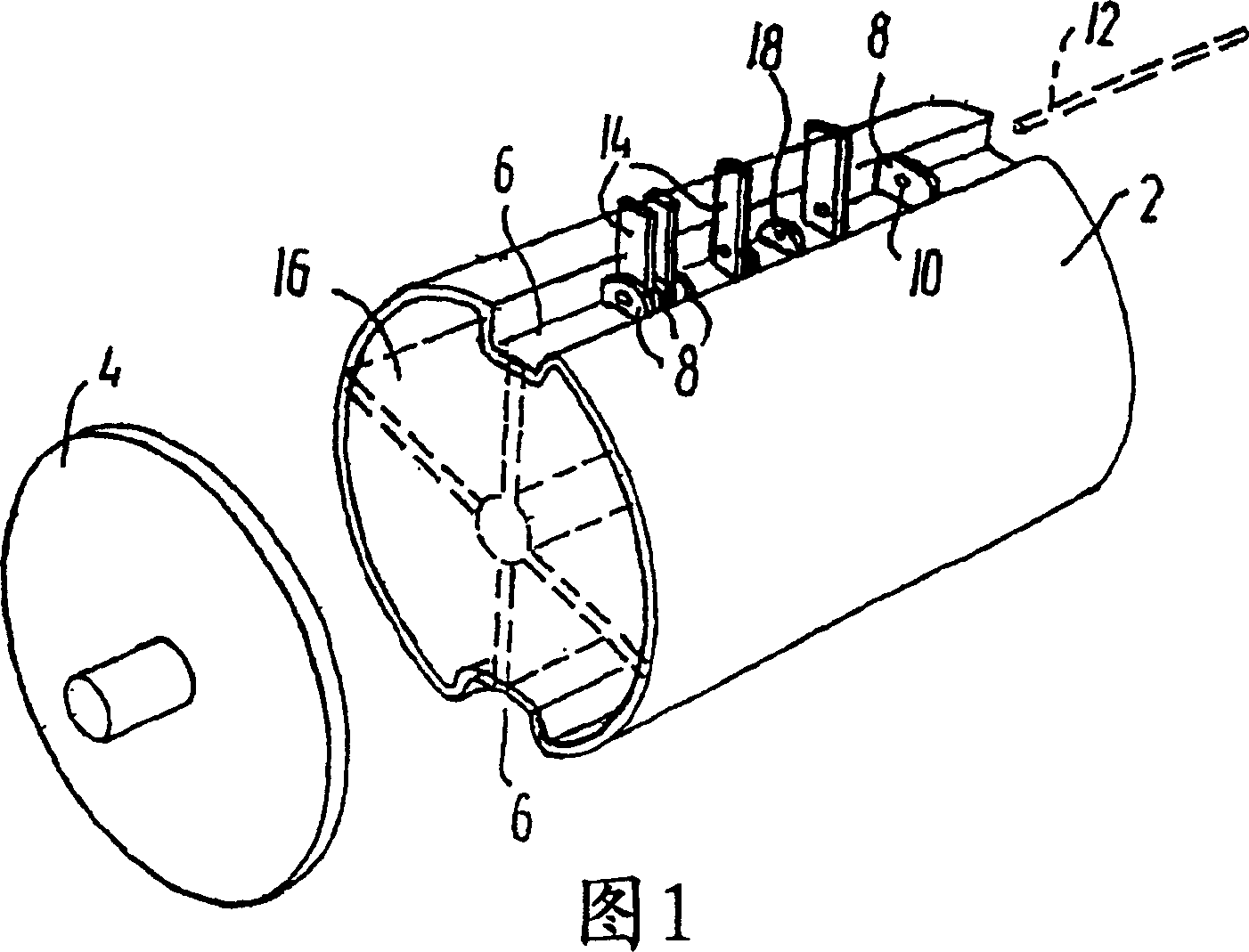
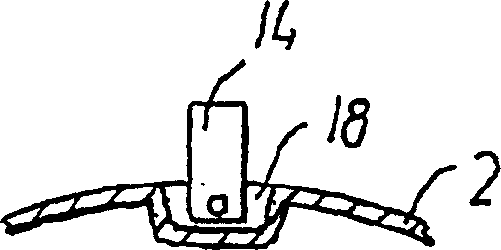
[0017] Referring to Figure 1, there is shown a sleeve 2, preferably made of sheet steel, provided with corresponding end portions 4. The profile of the sleeve 2 is provided with a pair of longitudinally extending grooves 6, in which a plurality of laterally positioned fastening plates 8 are fixed, and the fastening plates are provided with small holes 10 for accommodating a longitudinally extending Strut 12. In the openings between the plates 8 is provided a pivotally fixed series of radially outwardly extending chopping blades 14 pivotable about base holes for receiving said struts 12 . The sleeve 2 is stabilized by means of radially extending wings 16 located between the inner wall of the sleeve 2 and an extension 19 ′ of a central drive shaft 19 .

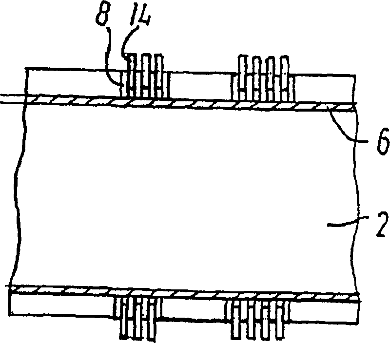
[0018] see image 3 , the series of chopping blades 14 in the two opposite grooves 6 shown in Fig. out) the en...


PUM


Abstract

In a rotor construction for a hammer or shredder mill, the rotor is formed by a cylindrical housing structure (2) whose transverse profile is formed as a drum-like surface comprising at least one longitudinal An extended groove (6) for receiving the base of the chopping blade. In the rotor structure, said at least one groove (6) is provided with chopping blade positioners (8, 18) in a fixed position for laterally fixing and stably accommodating said base for pivotally mounting said Shaft (12) for chopping blades (14).

Description

technical field [0001] The invention relates to a rotor for a hammer or shredder mill. Background technique [0002] A rotor for a hammer or shredder mill is a roller unit which has been fabricated as a stack or bundle of circular support plates, which are bordered by intervening circular baffles of smaller diameter than the support plates. spaced vertically. In this way, radially outwardly of each of these baffles, a circumferential groove is formed between adjacent opposing support plates, in which grooves radially outwardly extending chopper blades (chopper member) can be accommodated. ), the shredding blade is pivotally connected to a longitudinally extending shaft, and a positioning hole passing through it is provided in the support plate. The outwardly extending chopping blades cooperate with a surrounding sieve basket. [0003] It is known in the prior art that the rotor construction described above has a number of disadvantages, such as that the construction is un...

Claims


Application Information

Patent Timeline
Patent Type & Authority Patents(China)
IPC IPC(8): B02C13/00B02C13/04B02C13/28
CPCB02C13/04B02C13/28
Inventor 亨宁·约尔根森
Owner SPROUT MATADOR
Why Eureka
Try Eureka