
Holographic coupling element and its manufacturing method, and holographic laser unit and optical pickup device

A coupling element and optical pickup technology, applied in the direction of beam guiding device, optics, optical components, etc., can solve the problems of light loss, weakening of laser beam, and lower reliability, so as to reduce labor time, reduce labor time, reduce light loss effect

Inactive Publication Date: 2006-09-13
SHARP KK
View PDF3 Cites 0 Cited by
  • Summary
  • Abstract
  • Description
  • Claims
  • Application Information

AI Technical Summary

Problems solved by technology

[0011] In the case where the above-mentioned air layer is placed on the two hologram substrates, there is a problem that the refraction and scattering of light naturally lowers the light quantity of the laser beam to be focused on the optical recording medium and causes loss of the light quantity, thereby reducing reliability
[0012] Also, in the third to fifth related arts described above, two semiconductor laser devices are placed adjacent to each other at such a position that the optical axes of the laser beams emitted from the respective semiconductor laser devices become very coincident, whereby the two semiconductor laser devices Laser beams having different oscillation wavelengths emitted by the laser devices are respectively input to the first and second holograms, therefore, there is a problem that the laser beams emitted by the respective semiconductor laser devices are diffracted by the first and second holograms to cause different necessary light, thereby weakening the amount of the laser beam to be focused on the optical recording medium, thus reducing the utilization efficiency of the light
However, since the pitch of the diffraction gratings of the first and second holograms is smaller than that of the three-beam diffraction grating, it is difficult to provide the first and second holograms with a thickness that allows diffraction by only two semiconductors. Diffraction grating grooves for laser beams emitted by laser devices

Method used


Image

  • Holographic coupling element and its manufacturing method, and holographic laser unit and optical pickup device
  • Holographic coupling element and its manufacturing method, and holographic laser unit and optical pickup device
  • Holographic coupling element and its manufacturing method, and holographic laser unit and optical pickup device

Examples


Embodiment Construction

[0093] Referring now to the accompanying drawings, preferred embodiments of the present invention will be described in detail.

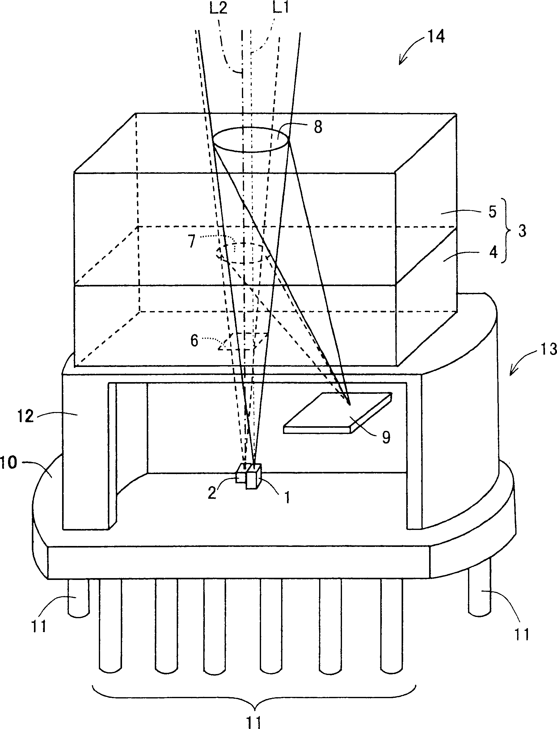
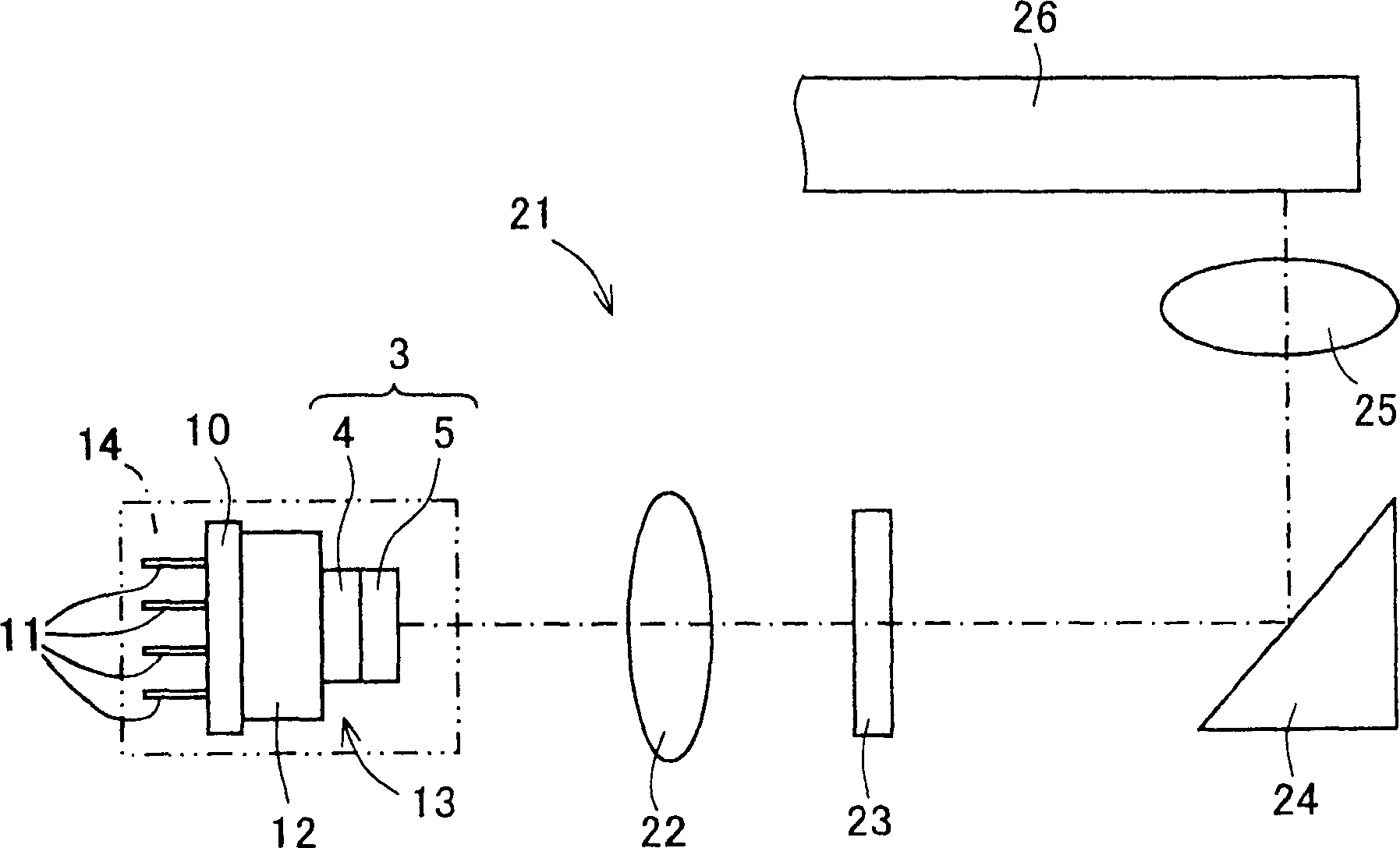
[0094] figure 1 A simplified perspective view showing the structure of a holographic laser unit 14 including a holographic coupling element 3 of an embodiment of the present invention. exist figure 1 , the cover 12 described later is partially cut away for display. The holographic laser unit 14 includes the holographic coupling element 3 and the semiconductor laser device 13 . The semiconductor laser device 13 includes a first semiconductor laser device 1 , a second semiconductor laser device 2 , a light receiving device 9 , a stem 10 , an electrode 11 , and a cover 12 . The holographic coupling element 3 includes a first polarization hologram substrate 4 as a first substrate and a second polarization hologram substrate 5 as a second substrate. The first polarization hologram substrate 4 includes a three-beam diffraction grating 6 and a first pol...


PUM

PropertyMeasurementUnit
wavelengthaaaaaaaaaa
transmittivityaaaaaaaaaa

Abstract

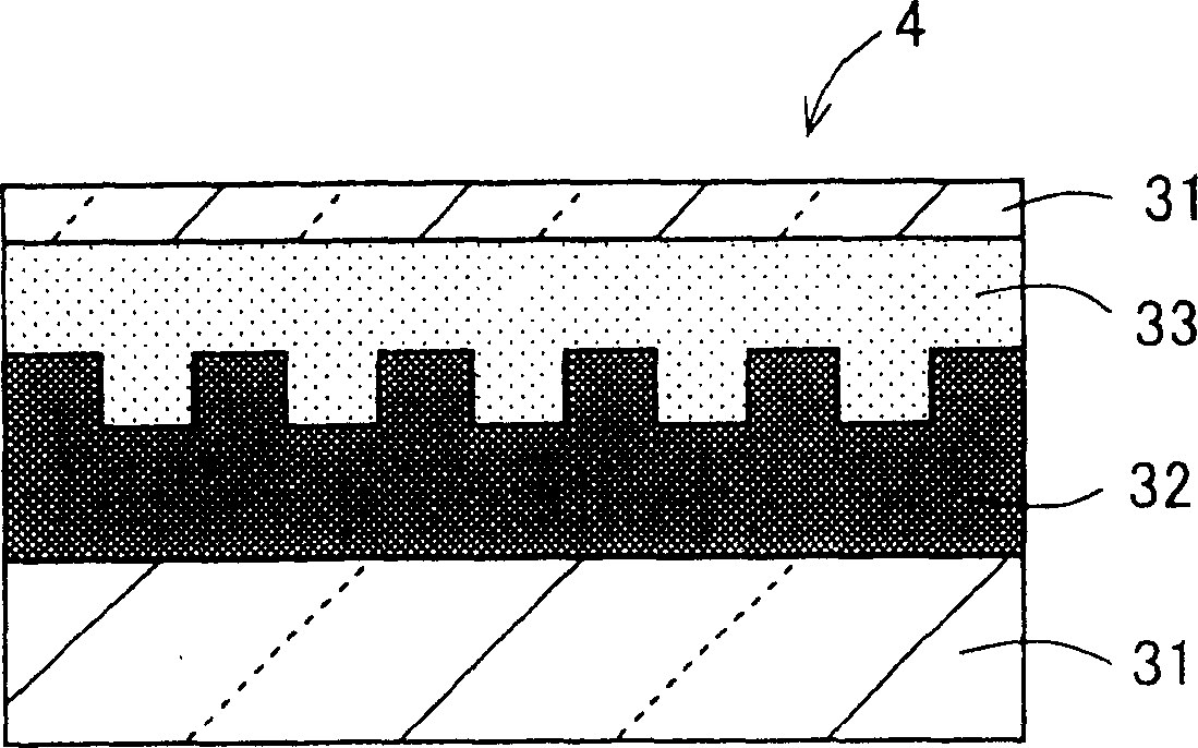
Provided is a hologram coupled member, its manufacturing method, a hologram laser unit, and an optical pickup apparatus. A birefringent layer 32 having a diffraction surface is formed on a transparent substrate 31, an isotropic overcoat layer 33 is formed on the diffraction surface of the birefringent layer 32 and, by forming the transparent substrate 31 on the isotropic overcoat layer 33, first and second polarizing hologram substrates 4, 5 are formed. A light transmitting adhesive is uniformly applied between the respective surfaces of the first and second polarizing hologram substrates 4, 5 facing each other to bond the first and second polarizing hologram substrates 4, 5. Thus, the hologram coupled member 3 in which an optical coupling layer 34 formed as a result of cure of the light transmitting adhesive is interposed is formed between the facing surfaces of the first and second polarizing hologram substrates 4, 5.

Description

technical field [0001] The present invention relates to a holographic coupling element and a manufacturing method thereof, as well as a holographic laser unit and an optical pick-up device, when reading information such as CD (Compact Disk, compact disc) and DVD (Digital Versatile Disk, digital versatile disc) and recording information to an optical recording When on the medium, the method and apparatus described above are preferably used. Background technique [0002] An optical pickup is used to read and record information from and to an optical disc-shaped recording medium (hereinafter, simply referred to as an optical recording medium). Conventionally, optical recording media called the CD family whose information is read and written only by light have been used, and therefore, when reading information from and writing information to an optical recording medium , using a semiconductor laser device capable of emitting an infrared wavelength laser beam with an oscillation...

Claims


Application Information

Patent Timeline
Patent Type & Authority Patents(China)
IPC IPC(8): G11B7/135G11B7/24G11B7/26G11B7/0065G02B5/18G02B5/32G02B27/10G11B7/00G11B7/09G11B7/125G11B7/1353G11B7/22
CPCG11B7/1353G02B27/1086G02B27/1073G02B27/0944G11B2007/0006G02B5/32G11B7/22
Inventor 高木辉一松原和德
Owner SHARP KK
Learn More