Flow path shunting device

A technology of branching device and flow channel, which is applied in the field of flow channel branching device, can solve the problems of branching device body enlargement, poor operation of electromagnetic coil, difficulty in abnormality, etc.

Inactive Publication Date: 2006-07-26
PANASONIC CORP
View PDF1 Cites 0 Cited by
  • Summary
  • Abstract
  • Description
  • Claims
  • Application Information

AI Technical Summary

Problems solved by technology

As a result, the operation of replacing the electromagnetic coil is difficult, and the foaming pressure of the foam insulation material will cause the foam insulation material to intrude into the gap between the expansion valve mounting part and the electromagnetic coil, which may cause malfunction of the electromagnetic coil.
In addition, when filling and injecting this kind of foam insulation material into the outer box, even if the electromagnetic expansion device is tilted, or the electromagnetic expansion valve is tilted due to the injection pressure, it is difficult to confirm the abnormality from the outside after filling.
If the electromagnetic expansion valve is arranged in an inclined manner, it will cause the problem that the control flow may be different from the flow rate at the time of device design.
[0015] In addition, if the electromagnetic coil is simply arranged outside the main body, there will also be a problem that the main body of the branch device will become larger.

Method used


Image

  • Flow path shunting device
  • Flow path shunting device
  • Flow path shunting device

Examples


Embodiment

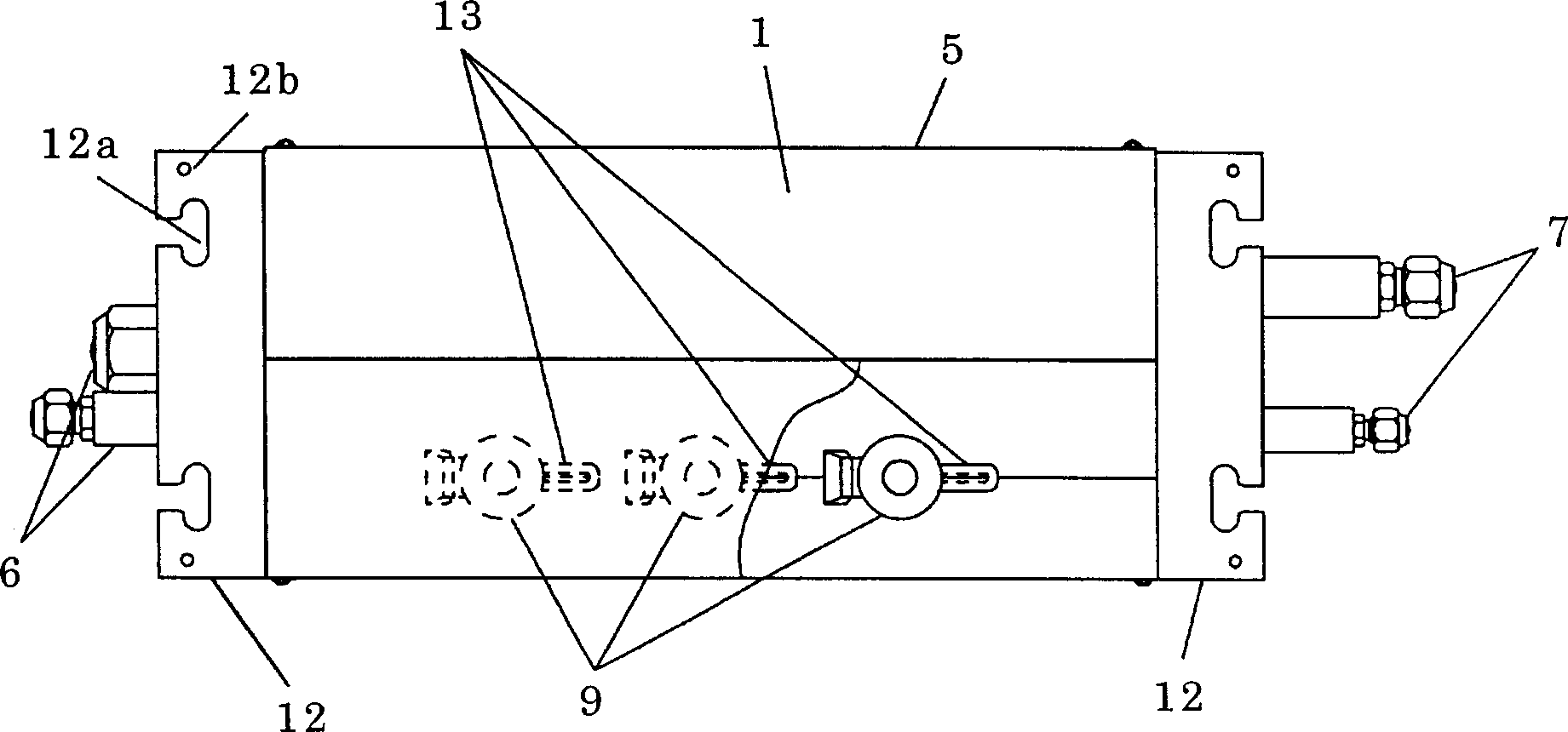
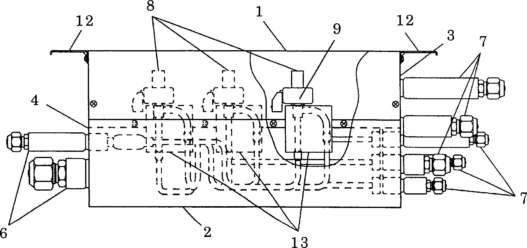
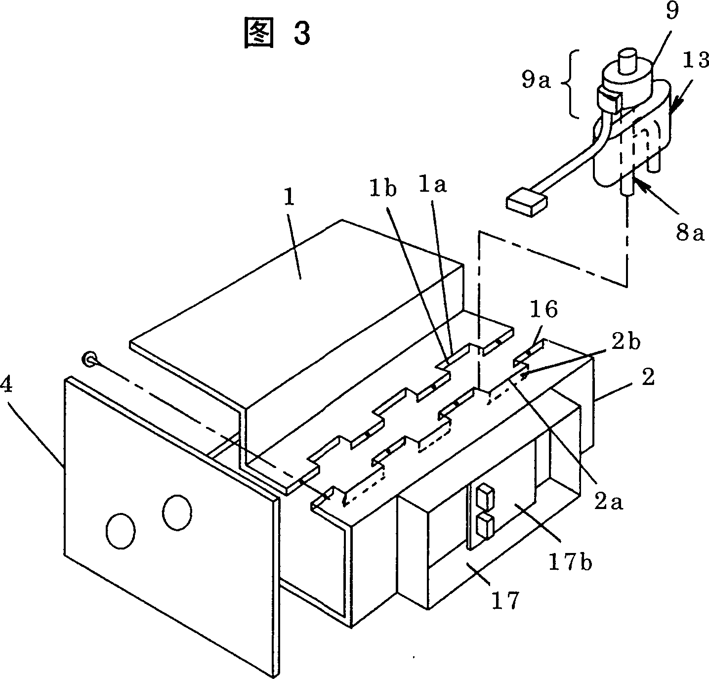
[0028] First, use figure 1 ~3 illustrates the structure of the refrigerant branching device of the embodiment of the present invention. figure 1 , figure 2 The configuration of the refrigerant branching device applied to a multi-room air conditioner is shown. in addition, figure 1 and figure 2 In , in order to clearly show the internal structure after assembly, a part of it is cut away.

[0029] The refrigerant branch device is based on the bottom of the outer box and the bottom plate 2 constituting a part of the side, and the outer contour is formed by the top plate 1, the right side plate 3, the left side plate 4 and the rear plate 5 which are detachably arranged with the bottom plate 2. In the structure for branching one flow path, the pipe connection port 6 connected to the connection pipe (not shown) drawn from the outdoor unit protrudes toward the left side plate 4 side. On the side of the right side plate 3 of the outer case, a plurality of protruding branch p...


PUM


Abstract

Provided is a compactly constitutable passage branching device easy in assembling, and reducing the number of part items in the passage branching device used for branching off one passage into a plurality. This passage branching device is constituted so as to fix an attitude by sandwiching this device by recessed parts formed on a top plate and a bottom plate by installing a shock absorbing heat insulating material in a passage part of a motor-driven expansion valve. In this case, an electromagnetic coil attachable-detachable to the motor-driven expansion valve is constituted so as to be exposed to the outer box surface side for allowing maintenance.

Description

technical field [0001] The present invention relates to a flow path branching device suitable for air conditioners and the like. The flow path branching device branches one flow path into a plurality of flow paths and has a device for controlling the flow rate of each branch flow path. Background technique [0002] Next, this conventional technology will be described using a refrigerant branching device applied to a multi-room air conditioner. A multi-room air conditioner has a configuration in which one outdoor unit is connected to a plurality of indoor units by refrigerant piping. [0003] As the connection form, when the outdoor unit is provided with a plurality of connection parts, the outdoor unit is connected to a system of connection piping, and the system connection piping is connected to the indoor unit in parallel, and there are other connection forms. etc., and the technology has been commercialized. [0004] A multi-room air conditioner can air-condition multip...

Claims


Application Information

Patent Timeline
Patent Type & Authority Patents(China)
IPC IPC(8): F25B41/00F24F5/00F25B41/06
Inventor 高本和久
Owner PANASONIC CORP
Why Eureka
Try Eureka