
Clamp capable of axial parallelly connecting cylinder shape temp sensor with pipe

A temperature sensor, axially parallel technology, used in thermometer parts, thermometers, pipes/pipe joints/fittings, etc., can solve the problem of high heat conduction resistance

Inactive Publication Date: 2006-03-22
DANFOSS AS
View PDF1 Cites 2 Cited by
  • Summary
  • Abstract
  • Description
  • Claims
  • Application Information

AI Technical Summary

Problems solved by technology

Correspondingly, the heat conduction resistance between the temperature sensor and the tube is relatively high

Method used


Image

  • Clamp capable of axial parallelly connecting cylinder shape temp sensor with pipe
  • Clamp capable of axial parallelly connecting cylinder shape temp sensor with pipe
  • Clamp capable of axial parallelly connecting cylinder shape temp sensor with pipe

Examples


Embodiment Construction

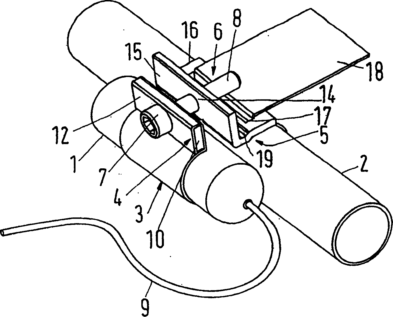
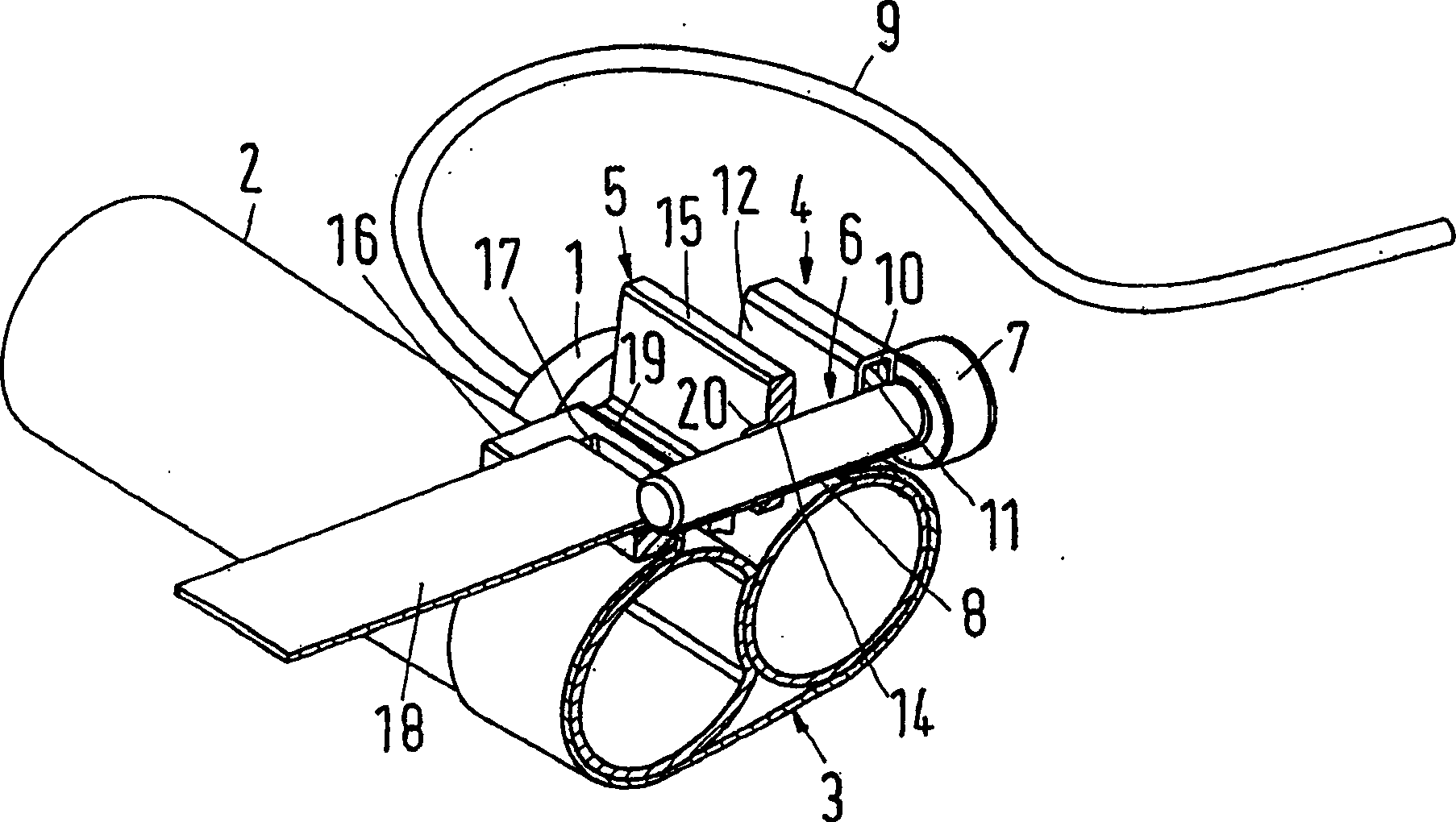
[0018] The clip shown is used to connect a cylindrical temperature sensor 1 of an expansion valve of a refrigeration plant or cooling unit to a tube 2 at the outlet of the evaporator of a refrigeration plant or cooling unit and to make the temperature sensor 1 and the tube 2 axial. touch each other in parallel.

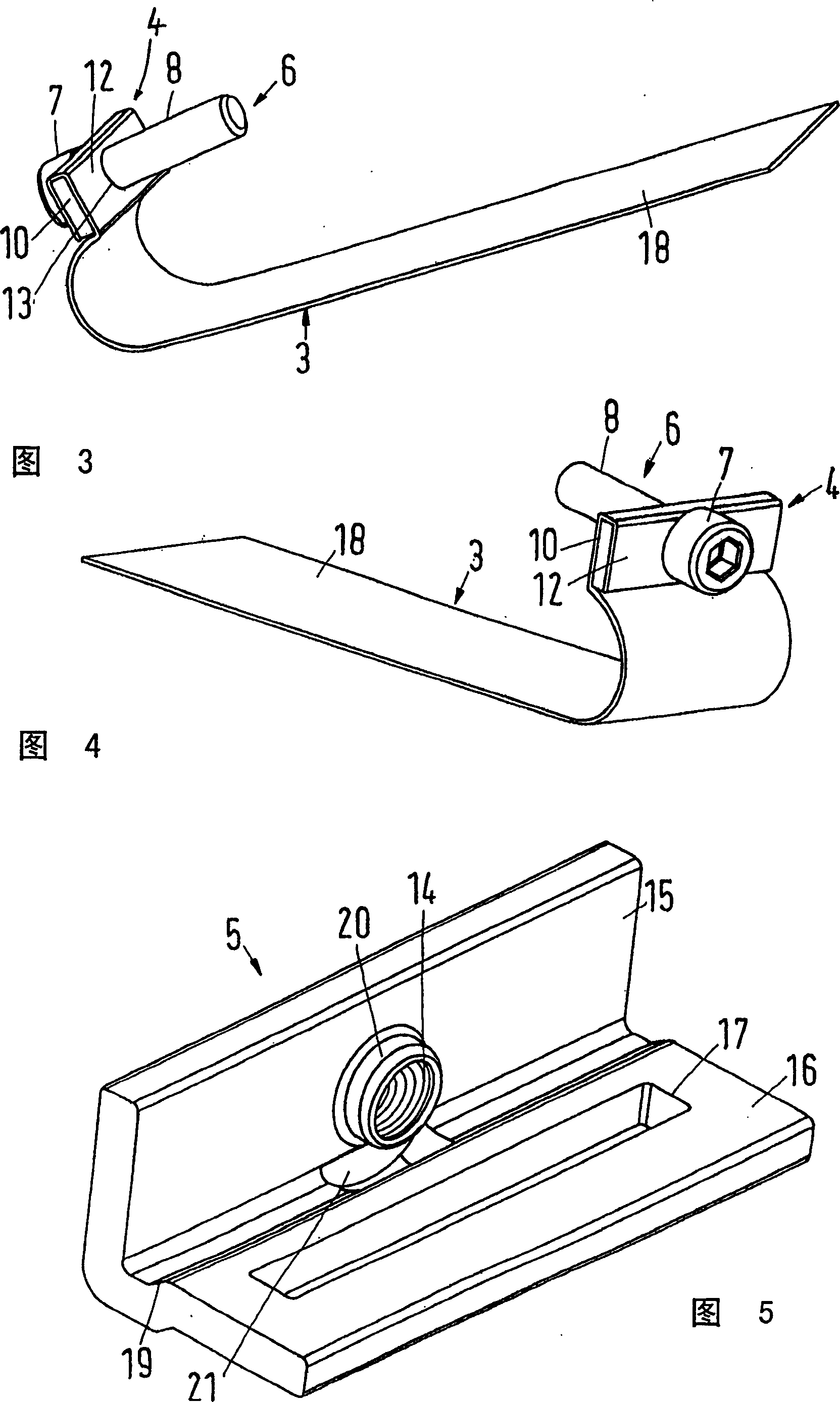
[0019] The clip shown comprises a bendable clamping collar 3 made of metal and preferably copper, a first jaw 4, a second jaw 5 in the form of a metal strip bent approximately 90°, and a metal strip with a Fastening bolt 6 with head 7 and threaded rod 8 .

[0020] The temperature sensor 1 is connected via a capillary 9 to the expansion valve (not shown).

[0021] Jaw 4 comprises a plate 10 with an unthreaded hole 11 . The first end 12 of the clamping jaw 3 is bent around the plate 10 so that it rests on both sides of the plate 10 . The first end 12 of the jaw 3 has a hole 13 on either side of the plate 10 (FIG. 3). The hole 13 is aligned with the unthreaded hole 1...


PUM


Abstract

A clamp for connecting a cylindrical temperature sensor 1 axis-parallel with a tube 2 has a bendable metallic tension band 3 which tension band on its one end portion 12 has a first jaw 4 and at its other end section 18 is shapewise connectable with a second jaw 5, and which clamp also has a tension screw 6. The tension screw 6 is inserted through a bore 11 in the first jaw 4 and is threaded through a threaded bore 14 in the second jaw 5. To be able to connect the sensor 1 and tube 2 rigidly with little heat transfer resistance the second jaw 5 has a bent plate with two legs 15, 16. The first leg 15 is provided with the threaded bore 14 and the second leg 16 with a slot 17 through which the other end section 18 can be passed. The tension band length is so chosen that the other end section 18 after the wrapping of the tension band 3 around the temperature sensor 1 and the tube 2 as well as its being passed through the slot 17 is bendable down onto the second leg 16. The tension screw length is so chosen that after its tightening it lies on the bent down end section 18.

Description

technical field [0001] The invention relates to a clamp for axially parallel connection of a cylindrical temperature sensor with a pipe in mutual contact between the temperature sensor and the pipe, which has a bendable metal clamp with a first clamp on one end. A clamping jaw and it also has a second clamping jaw which is positively connected with the second end of the fastening band and a fastening bolt, wherein the tightened fastening bolt passes through the hole in the first clamping jaw and is Screw through the threaded hole in the second jaw. Background technique [0002] In this known clip (US2863203), the second jaw has a plate nut. The second end of the fastening hoop has multiple groups of holes arranged longitudinally apart from the fastening hoop. The nut has two projections which, depending on the respective diameters of the temperature sensor and the tube and thus the required effective length of the clamp, engage in a set of holes so that the nut is positive...

Claims


Application Information

Patent Timeline
IPC IPC(8): F25B41/04F16L3/233F16L3/137F16L3/237
CPCF16L3/237F16L3/137Y10T24/1427G01K1/14
Inventor J·E·拉斯穆森B·S·汉森
Owner DANFOSS AS
Learn More