Light stuffing mold member for cast-in-situ steel concrete

A reinforced concrete, lightweight technology, applied in building components, building structures, floor slabs, etc., can solve the problems of unfavorable earthquake resistance and material saving, heavy floor weight, inconvenient production, etc. The effect of convenient transportation

Inactive Publication Date: 2006-02-22
湖南邱则有专利战略策划有限公司
View PDF2 Cites 0 Cited by
  • Summary
  • Abstract
  • Description
  • Claims
  • Application Information

AI Technical Summary

Problems solved by technology

However, after this type of formwork member is used as a carcass in the cast-in-place reinforced concrete hollow structure floor, the weight of the formed floor is still relatively heavy, which is not conducive to earthquake resistance and material saving. At the same time, the production is inconvenient and the cost is high. Therefore, the development of A new type of light-weight tire mold member for filling cast-in-place reinforced concrete has been urgently needed

Method used


Image

  • Light stuffing mold member for cast-in-situ steel concrete
  • Light stuffing mold member for cast-in-situ steel concrete
  • Light stuffing mold member for cast-in-situ steel concrete

Examples


Embodiment Construction

[0042] The present invention will be further described below in conjunction with drawings and embodiments.

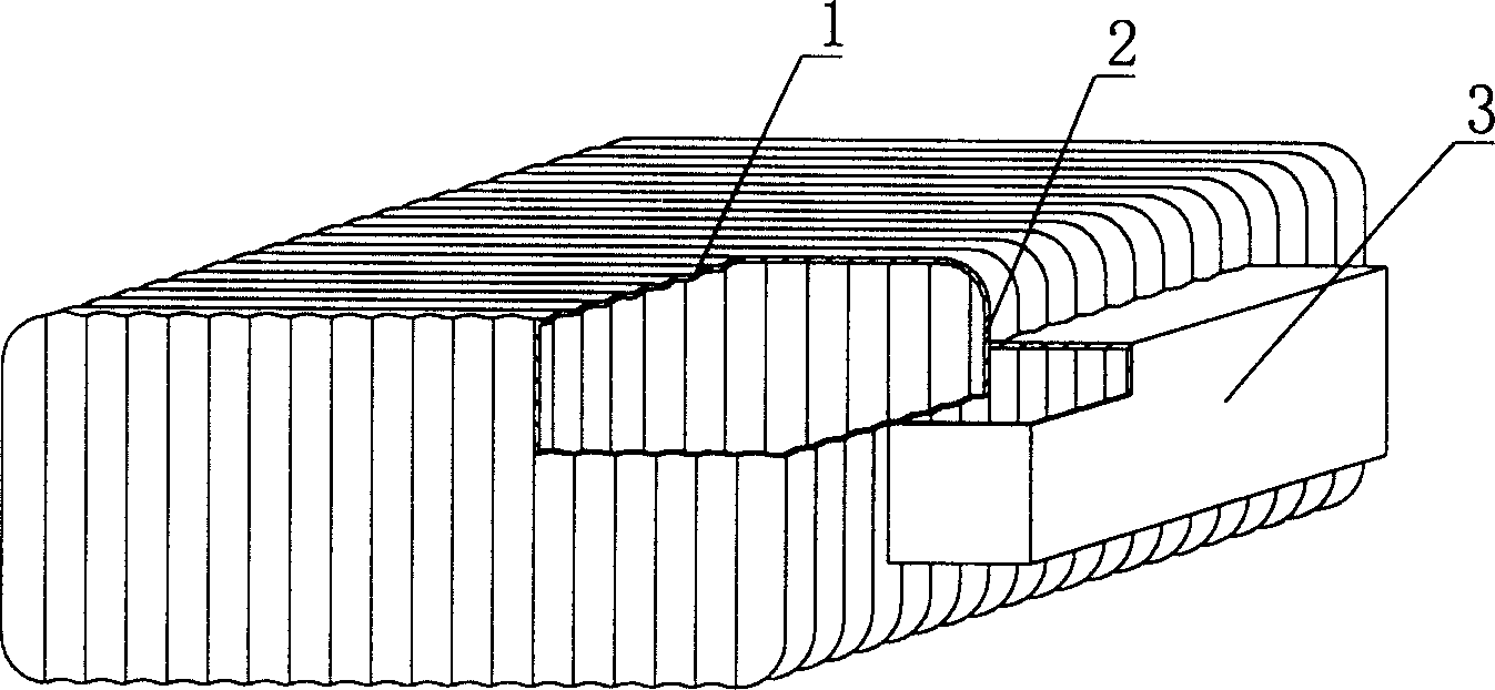
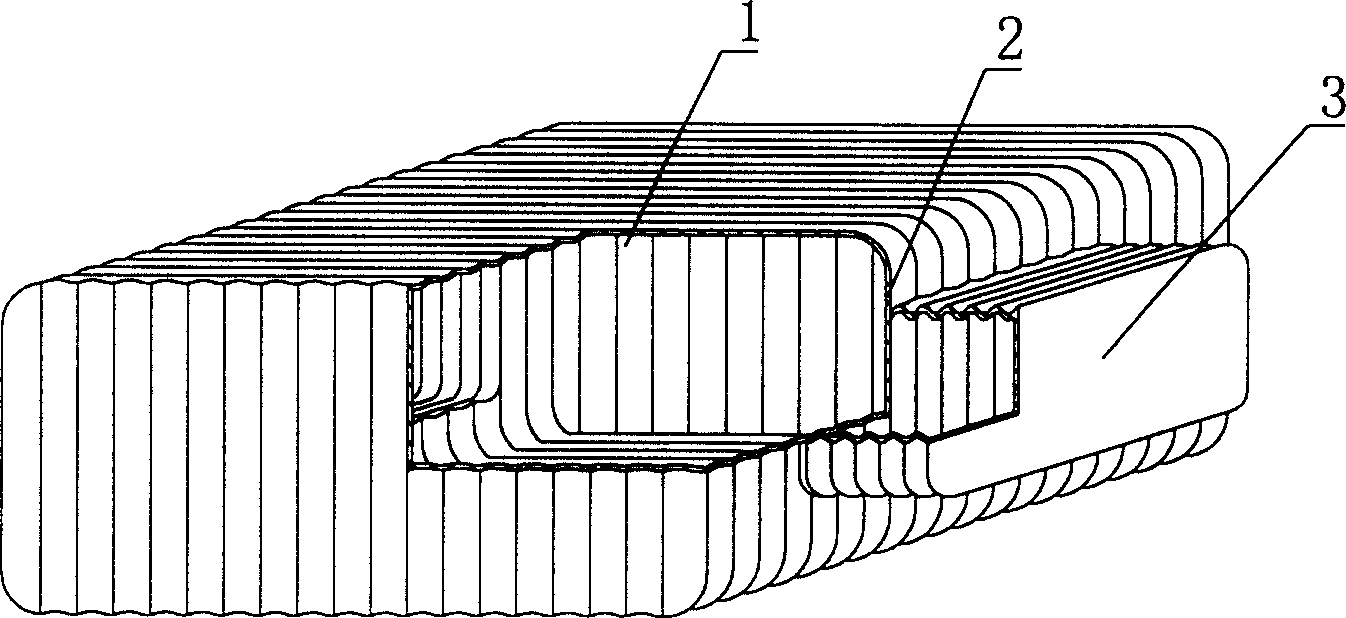
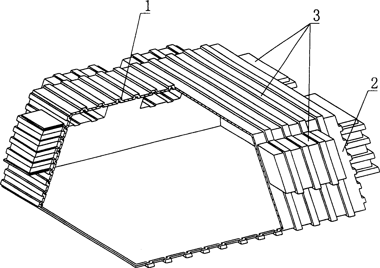
[0043] As shown in the drawings, the present invention includes a carcass 1, which is characterized in that the carcass 1 is a corrugated carcass, and there is at least one protruding module 3 on at least one side 2 of the corrugated carcass 1, and the module 3 is a corrugated module. figure 1 It is a structural schematic diagram of Embodiment 1 of the present invention. In each accompanying drawing, 1 is a carcass, 2 is the side of the carcass, and 3 is a protruding module. In each accompanying drawing, those with the same number have the same description. Such as figure 1 Among them, the carcass 1 is a corrugated carcass, and there are protruding modules 3 on the side 2 of the corrugated carcass 1 . figure 2 It is a structural schematic diagram of Embodiment 2 of the present invention, and its module 3 is a corrugated module.

[0044] The present invention lies in...


PUM


Abstract

The light stuffing mold member for in-situ cast reinforced concrete is one corrugated stuffing mold with at least protrudent block on its one side. After the light stuffing mold member is used in reinforced structure floor board, in-situ cast concrete rib of truss rod is formed, and the in-situ cast concrete rib has greatly reduced weight and saved material consumption, resulting in reduced floor board weight and raised antiseismic performance. With the features of light weight, high strength, simple structure, convenient construction and transport, etc, the light stuffing mold member is suitable for use in in-situ cast hollow beam-less reinforced concrete floor board as well as roofing, base board, wall and hollow bridge.

Description

(1) Technical field [0001] The invention relates to a lightweight tire mold component for filling cast-in-place reinforced concrete. (2) Background technology [0002] At present, most buildings with brick-concrete structure and frame structure use prefabricated hollow-core slabs as floor slabs, which have the advantages of fast construction speed and low cost. However, because there is no firm connection between two adjacent prefabricated hollow slabs, only cement mortar is used to fill the joints, so the integrity is poor, which is not conducive to earthquake resistance, and cracks and water seepage often occur in the gaps. In order to solve the above problems, many buildings adopt the method of cast-in-place concrete floor slabs (solid and hollow). Although the problems of earthquake resistance and cracking have been solved, a large number of templates are used during construction, which not only increases the cost, but also slows down the construction speed and prolongs ...

Claims


Application Information

Patent Timeline
Patent Type & Authority Patents(China)
IPC IPC(8): E04B5/36
Inventor 邱则有
Owner 湖南邱则有专利战略策划有限公司
Why Eureka
Try Eureka