Cathode-ray tube

A cathode ray tube, cathode technology, applied in the direction of cathode ray tube/electron beam tube, discharge tube, electrode device and related components, etc., can solve the problems of electron beam bombardment of electrodes, high current, unable to provide enough real and bright images, etc.

Inactive Publication Date: 2006-01-11
LG PHILIPS DISPLAY KOREA CO LTD
View PDF1 Cites 0 Cited by
  • Summary
  • Abstract
  • Description
  • Claims
  • Application Information

AI Technical Summary

Problems solved by technology

[0026] However, the above efforts only bring about the problem of vertically elongating the spot size in the center of the screen due to divergence
[0027] In other respects, due to the great development of Internet technology, more and more people now watch moving images on computer monitors, so electron guns with high brightness for computer monitors are introduced because monitor cathode ray tubes cannot Provides a sufficiently realistic and bright picture like a TV cathode ray tube
[0028] But this electron gun consumes 3 times more current than a normal electron gun
Worse is that as the current draw increases, the light spot becomes larger across the screen, and due to the larger light spot, the resolution decreases
[0029] In short, due to more current applied to the electron gun, although grooves are formed on the second electrode to control the electron beam, the screen resolution is still low
[0030] In addition, as shown in Figure 7, the increase in current capacity increases the diameter of the electron beam (D'>D), which will cause the electron beam to bombard the electrode, thereby destroying the circuit in it

Method used


Image

  • Cathode-ray tube
  • Cathode-ray tube
  • Cathode-ray tube

Examples


Embodiment Construction

[0053] A cathode ray tube according to a preferred embodiment of the present invention will be described in detail below with reference to the accompanying drawings.

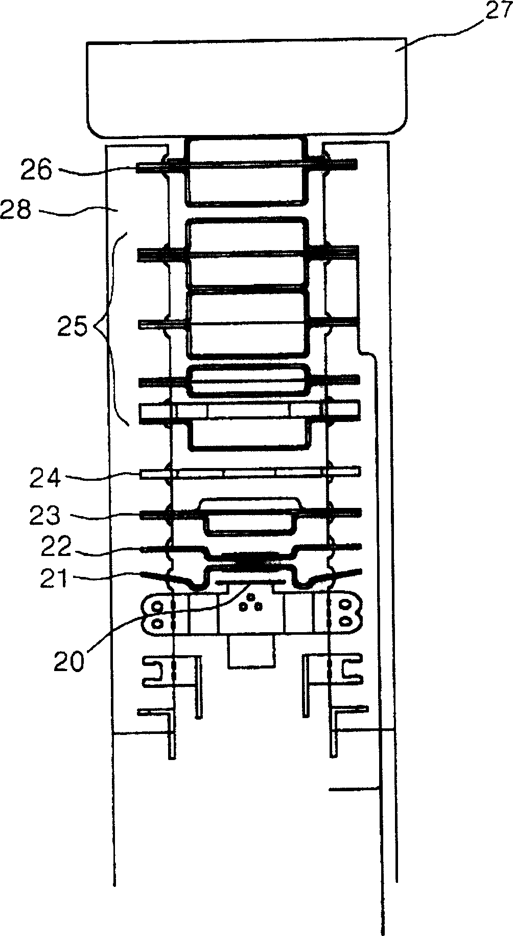
[0054] Figure 8 An electron gun of a cathode ray tube according to the invention is shown.

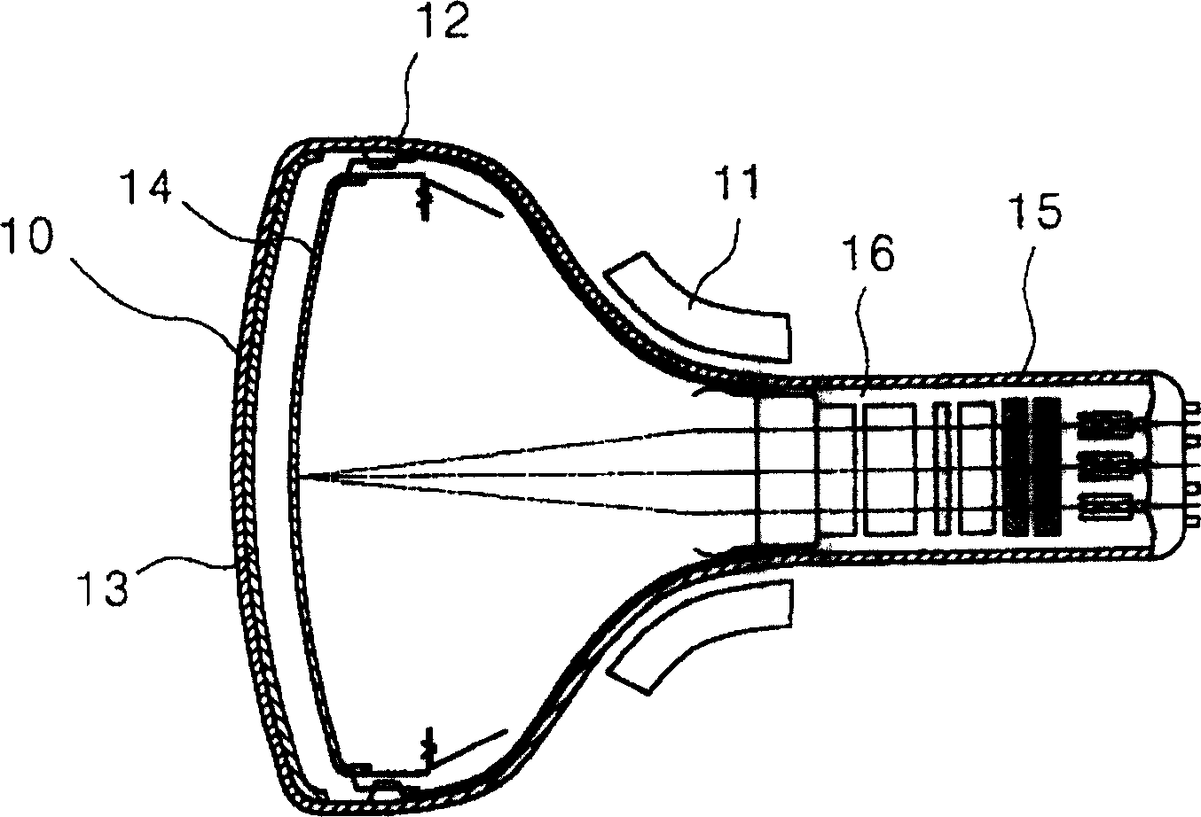
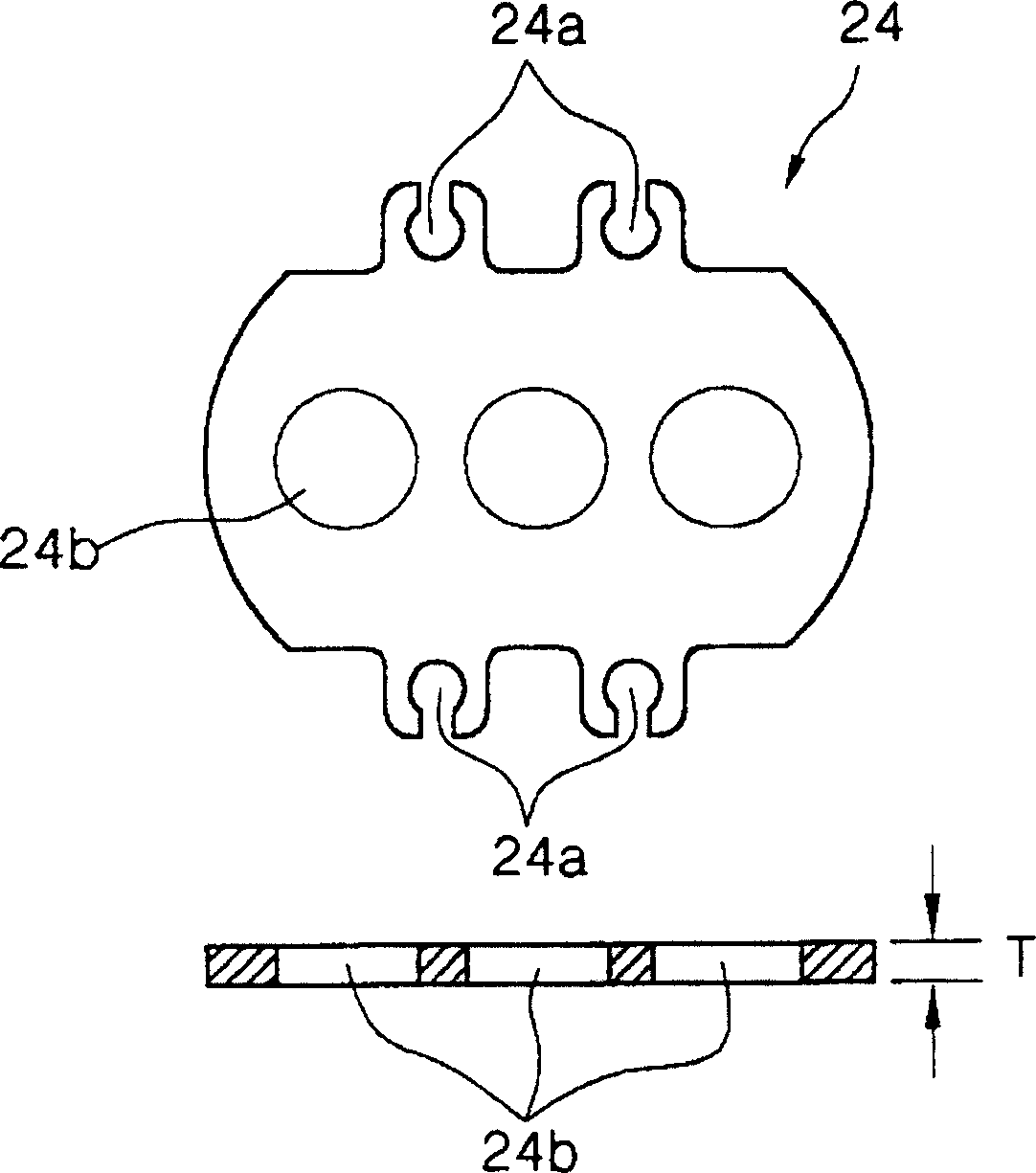
[0055] refer to Figure 8 , the electron gun includes: a cathode 20, which is used as an electron beam generator; a first electrode 21 and a second electrode 22, and their potential difference is combined with the cathode 20 to form a front focus lens; the third electrode 23, the fourth electrode 24 and the fifth electrode The electrodes 25 constitute a front main lens for converging electron beams; and the fifth electrode 25 and sixth electrode 26 are combined with the front main lens to form a main lens for converging electron beams on the fluorescent screen.

[0056] In addition, the electron gun has a main component, that is, a shielding cover 27, which is welded to the sixth electrode 26 to shield external electric...


PUM


Abstract

Disclosed is a cathode ray tube with an electron gun capable of improving a resolution of an image by preventing electron beams from striking electrodes and efficiently controlling a spot size that is susceptible to a change in current capacity.

Description

technical field [0001] The present invention relates to a cathode ray tube, and more particularly, to a cathode ray tube having an electron gun capable of preventing electron beams from bombarding electrodes and effectively controlling the size of a spot susceptible to changes in current capacity, thereby enabling improved image resolution. Background technique [0002] FIG. 1 is an illustration of a conventional conventional cathode ray tube. [0003] As shown in Figure 1, this cathode ray tube comprises panel 1, and fluorescent screen 13 is arranged on its inner surface, is coated with R, G, B phosphor (or phosphorus) on the screen; In order to keep the vacuum state in the tube; the electron gun is installed in the neck 15 of the glass bulb 12 and is used to emit electron beams; the deflection yoke 11 is used to deflect the electron beams emitted by the electron beam 16; and the shadow mask 14 has the color selection function of the electron beams deflected by the deflect...

Claims


Application Information

Patent Timeline
Patent Type & Authority Patents(China)
IPC IPC(8): H01J29/48H01J29/46H01J29/50H01J29/70
CPCH01J2229/4844H01J2229/4824H01J2229/4837H01J29/503H01J29/488
Inventor 崔镇烈
Owner LG PHILIPS DISPLAY KOREA CO LTD
Why Eureka
Try Eureka