Full-plane soft circuit board connector

A flexible circuit board, full-plane technology, applied in the direction of circuits, connections, instruments, etc., can solve the problems of flexible circuit board connector 10 such as inconvenient operation, limited force torque, laborious operation, etc.

Inactive Publication Date: 2005-10-26
P TWO ELECTRONICS SHENZHEN
View PDF0 Cites 0 Cited by
  • Summary
  • Abstract
  • Description
  • Claims
  • Application Information

AI Technical Summary

Problems solved by technology

[0003] It’s just that the structure of the above-mentioned insulating body 20 is a closed frame structure with an upper side wall 21 and a lower side wall 22, and the plug terminals 25 are enclosed inside the frame. This structural design makes the movable cover 30 naturally unable to become an insulating The upper side wall part of the body 20, so the pivot point for the locking cover 30 to be flipped or closed must be set in the middle of the upper pin 26 and the lower pin 27 of the second half of the plug-in terminal 25, and cannot be set in the In the frame structure of the insulating body 20, the space for setting the locking cover 30 is limited, and the force torque for lifting or closing the locking cover 30 is also limited, which is usually relatively short and the operation is laborious. Moreover, the direction of the closing operation , and towards the rear direction of the insulating body 20, on the whole, the operation of the existing flexible circuit board connector 10 is not convenient
[0004] In addition, the structure of the existing flexible circuit board connector 10 usually does not have the function of preventing electromagnetic wave interference (EMI), so it is necessary to add a device for shielding electromagnetic waves to improve the performance of the flexible circuit board connector

Method used


Image

  • Full-plane soft circuit board connector
  • Full-plane soft circuit board connector
  • Full-plane soft circuit board connector

Examples


Embodiment approach

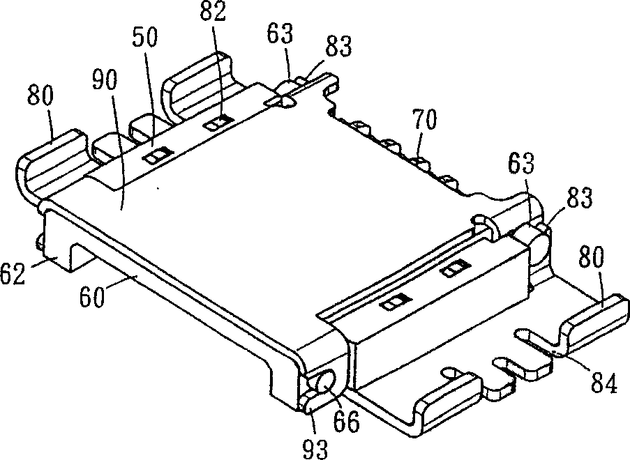
[0063] see Figure 6 to Figure 9 When the flexible circuit board 15 is to be plugged in, the movable upper cover 60 of the full-plane flexible circuit board connector 40 is lifted to the maximum angle to the rear, and the opening groove 51 of the concave body 50 is fully exposed to facilitate the flexible circuit board 15. The permanent circuit board 15 is plugged in. At this time, because the upper pin 71 of the plug terminal 70 is separated from the protruding shaft 65 of the movable upper cover 60, the front section of the upper pin 71 does not have a tendency to press downward. Therefore, the flexible circuit board 15 can be easily plugged into the insertion groove 75 of the plug terminal 70 along the side ribs 52 on the left and right sides of the opening groove 51 of the concave body 50, and is connected with the plug terminal 70. To form an electrical connection, then, the movable upper cover 60 is covered in the opening groove 51 of the concave body 50 forward. Due to...


PUM


Abstract

The upper and side walls of the connector comprises the movable cover able to be lifted rearward and closed forwards. With the cover being lifted, the connector is exposed in an opened space so that a soft circuit board is easy to be inserted and connected to the socket joint firmly. Then, the cover is closed. Thus the soft board will not get loose. The metal shield plate can be set on the cover so as to prevent interference of electromagnetic wave.

Description

technical field [0001] The present invention is a full-plane flexible circuit board connector with an open space, especially a movable upper cover that can be lifted and closed, which can facilitate the connection between the flexible circuit board and the exposed plug-in terminals in the open space. It is a full-flat flexible circuit board connector that can be plugged in and has the function of preventing electromagnetic wave interference. Background technique [0002] The structure and use state of existing flexible printed circuit board connector 10 are roughly as figure 1 and figure 2 As shown, it is composed of a rectangular insulating body 20, a long rectangular locking cover 30 and several plug-in terminals 25, wherein the insulating body 20 is a closed frame structure consisting of an upper side wall 21, a lower side wall 22 and a The upper side wall 21 and the side walls on the left and right sides of the lower side wall 22 are jointly enclosed, and the front op...

Claims


Application Information

Patent Timeline
Patent Type & Authority Patents(China)
IPC IPC(8): G06K7/06H01R12/77
Inventor 邱显钰
Owner P TWO ELECTRONICS SHENZHEN
Why Eureka
Try Eureka