Buffer programming method based on blank region redistribution

A technology of buffer and blank area, applied in the field of BBL

Inactive Publication Date: 2005-10-19
TSINGHUA UNIV
View PDF0 Cites 0 Cited by
  • Summary
  • Abstract
  • Description
  • Claims
  • Application Information

AI Technical Summary

Problems solved by technology

Among the many buffer planning algorithms, there is no method to optimize the blank area in the layout to make better use of the blank area to improve the delay characteristics of the circuit

Method used


Image

  • Buffer programming method based on blank region redistribution
  • Buffer programming method based on blank region redistribution
  • Buffer programming method based on blank region redistribution

Examples


Embodiment Construction

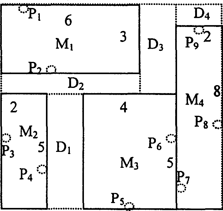
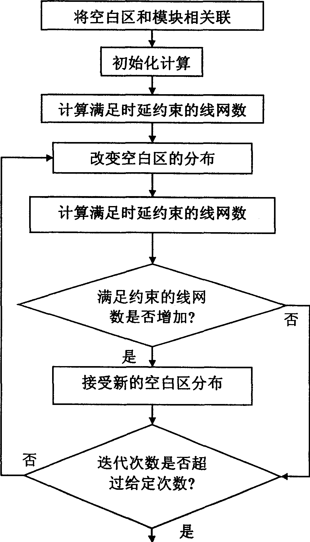
[0073] The present invention can be implemented under different layout plans / layout representations based on rectangular divisions (that is to say, this type of layout representation divides the chip into rectangular areas whose number is greater than or equal to the number of modules, and each rectangular area has at most one module) . This part adopts the layout result represented by CBL as an example of the present invention, and adopts the Elmore time delay model as the model of time delay calculation. combine figure 2 The flowchart of using the method of the present invention to carry out floorplanning based on redistribution of white space. Table 1 is the definition of some variables.

[0074] r

Wire resistance per unit length (Ω / μm)

c

Line capacitance per unit length (fF / μm)

T b

Buffer Intrinsic Latency (ps)

C b

Buffer Input Capacitance (fF)

R b

Buffer output resistance (Ω)

R d...


PUM


Abstract

A buffer planning method based on the relocation of empty areas includes finding out the relative number of buffers and the number of wire-meshes according to wire-mesh delay restriction, modifying the distribution of empty areas by iterating several times, updating the associated wire-mesh information, recalculating the number of wire mashes for meeting the delay restriction, and replacing original distribution of empty areas.

Description

technical field [0001] The buffer planning method based on blank area reallocation belongs to the field of computer aided design of integrated circuits, especially the field of BBL (Building Block Layout). Background technique [0002] Physical design is an important part of the very large scale integration (VLSI) design process. The computer-aided design technology related to this is called automatic layout. The manufacturing process of integrated circuits has entered from the current deep submicron (DSM) to ultra-deep submicron (VDSM), and the design scale of integrated circuits is also changing from very large scale (VLSI), very large scale (ULSI) to G large scale (GSI) With the rapid development of the circuit, the complexity of the circuit has increased sharply, making the hierarchical circuit design and the reuse technology of the circuit module receive unprecedented attention from the academic and industrial circles. The emergence of a large number of intellectual p...

Claims


Application Information

Patent Timeline
IPC IPC(8): G06F17/50
Inventor 洪先龙陈松董社勤马昱春
Owner TSINGHUA UNIV
Why Eureka
Try Eureka