
Sigma-delta A/D converter

A technology of analog-to-digital converter and digital-to-analog converter, applied in the field of sigma-delta analog-to-digital converter

Inactive Publication Date: 2005-07-13
YOKOGAWA ELECTRIC CORP
View PDF1 Cites 0 Cited by
  • Summary
  • Abstract
  • Description
  • Claims
  • Application Information

AI Technical Summary

Problems solved by technology

Therefore, the operation of the analog-to-digital converter must make the overall current consumption less than 4mA
therefore, Figure 4 There is a problem with the sigma-delta analog-to-digital converter shown

Method used


Image

  • Sigma-delta A/D converter
  • Sigma-delta A/D converter
  • Sigma-delta A/D converter

Examples


Embodiment Construction

[0047] The present invention will be described in detail below using the drawings.

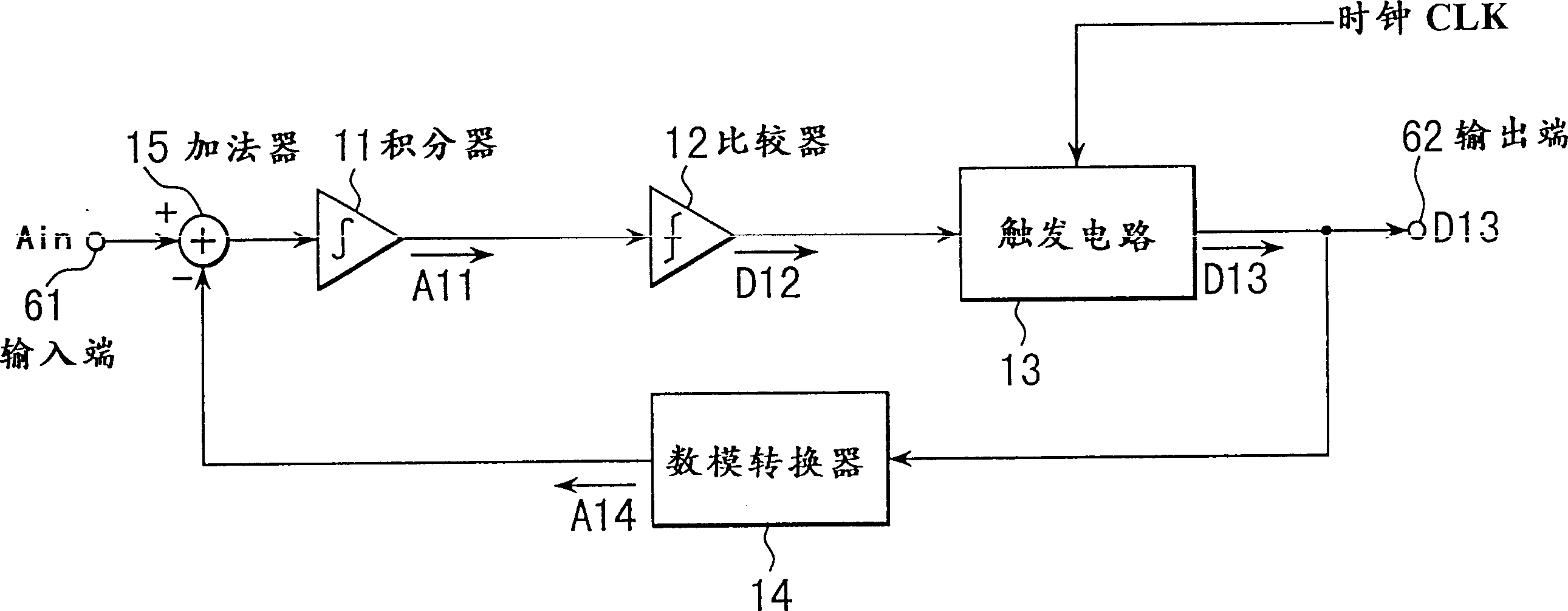
[0048] Figure 5 is a simplified block diagram representing a sigma-delta analog-to-digital converter in accordance with the present invention. In the figure, the pair and illustrate the traditional sigma-delta analog-to-digital converter problem Figure 4 Components that behave in the same way are given the same designations and are not explained again.

[0049] Figure 5 different from Figure 4 That is, the isolation circuit is located between the comparator 12 and the flip-flop 13 and between the output of the flip-flop 13 and the digital-to-analog converter 14 .

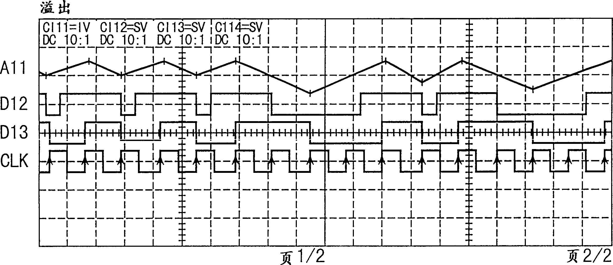
[0050] The output D12 of the comparator 12 can be easily isolated from the output D13 of the flip-flop circuit 13, since both outputs refer to binary high or low signals. and Figure 4 The circuit is different, the high-frequency clock signal CLK does not pass Figure 5 Circuit isolation circuit. Furthermore, the output ...


PUM


Abstract

A sigma-delta analog-to-digital converter for instruments such as two-wire eddy current meters. The input terminal of the converter, the adder, the integrator, the comparator and the trigger circuit are connected in series, the output signal of the trigger circuit is connected to the output terminal of the converter, and the output signal is fed back to the adder through the digital-to-analog converter. Thus, the converter acts as a sigma-delta analog-to-digital converter to output a pulse density signal corresponding to a given input signal. The output of the comparator is isolated from the input of the trigger circuit, and the output of the trigger circuit is isolated from the input of the digital-to-analog converter, so as to reduce power consumption.

Description

technical field [0001] The invention relates to a sigma-delta analog-to-digital converter for a two-wire eddy current meter which uses a sensor to detect the eddy current frequency based on the flow rate of the liquid under measurement and converts the detected analog signal into a digital flow rate Signal, and output the measured flow rate to the external device in the form of 4-20mA current signal, which is also used as the working energy of the external device. More precisely, the invention relates to sigma-delta analog-to-digital converters in which the means for isolating the input signal are improved in order to reduce power consumption. Background technique [0002] refer to figure 1 A conventional eddy current meter structure is described. In the figure, an input signal from a sensor 1 for detecting a vortex generated by a vortex injector is amplified by an amplifier 2 and input to an anti-aliasing filter 3 . The signal input to the anti-aliasing filter 3 is there...

Claims


Application Information

Patent Timeline
IPC IPC(8): G01F1/32H03M3/02
CPCH03M3/32H03M3/43H03M3/456G01F1/3287
Inventor 和田正巳
Owner YOKOGAWA ELECTRIC CORP
Learn More