Optical delay structure

A technology of optical delay and optical components, applied in the field of optics, can solve the problems of complex and time-consuming disassembly and debugging, low speed of the stage, and long scanning time, and achieve the effects of convenient laying and debugging, high precision, and short scanning time.

Pending Publication Date: 2021-09-21
UNIV OF ELECTRONIC SCI & TECH OF CHINA +1
View PDF3 Cites 0 Cited by
  • Summary
  • Abstract
  • Description
  • Claims
  • Application Information

AI Technical Summary

Problems solved by technology

In order to ensure high displacement accuracy and stability, the speed of the displacement stage is often low, so the single scan time is long, usually reaching several minutes or more
Especially when large-scale scanning is required, the size of the required translation stage is very large, and the scanning time is as long as several hours. The measurement efficiency is very low, and the volume of the whole system will be very large, occupying a lot of space, and disassembly and debugging are also abnormal. Complicated and time-consuming, it has gradually failed to meet the current needs

Method used


Image

  • Optical delay structure
  • Optical delay structure
  • Optical delay structure

Examples


Embodiment Construction

[0024] Various embodiments of the present invention will be described in more detail below with reference to the accompanying drawings. In each of the drawings, the same elements are expressed by the same or similar reference numerals. For the sake of clarity, the various parts in the drawings are not drawn.

[0025] DETAILED DESCRIPTION OF THE PREFERRED EMBODIMENTS

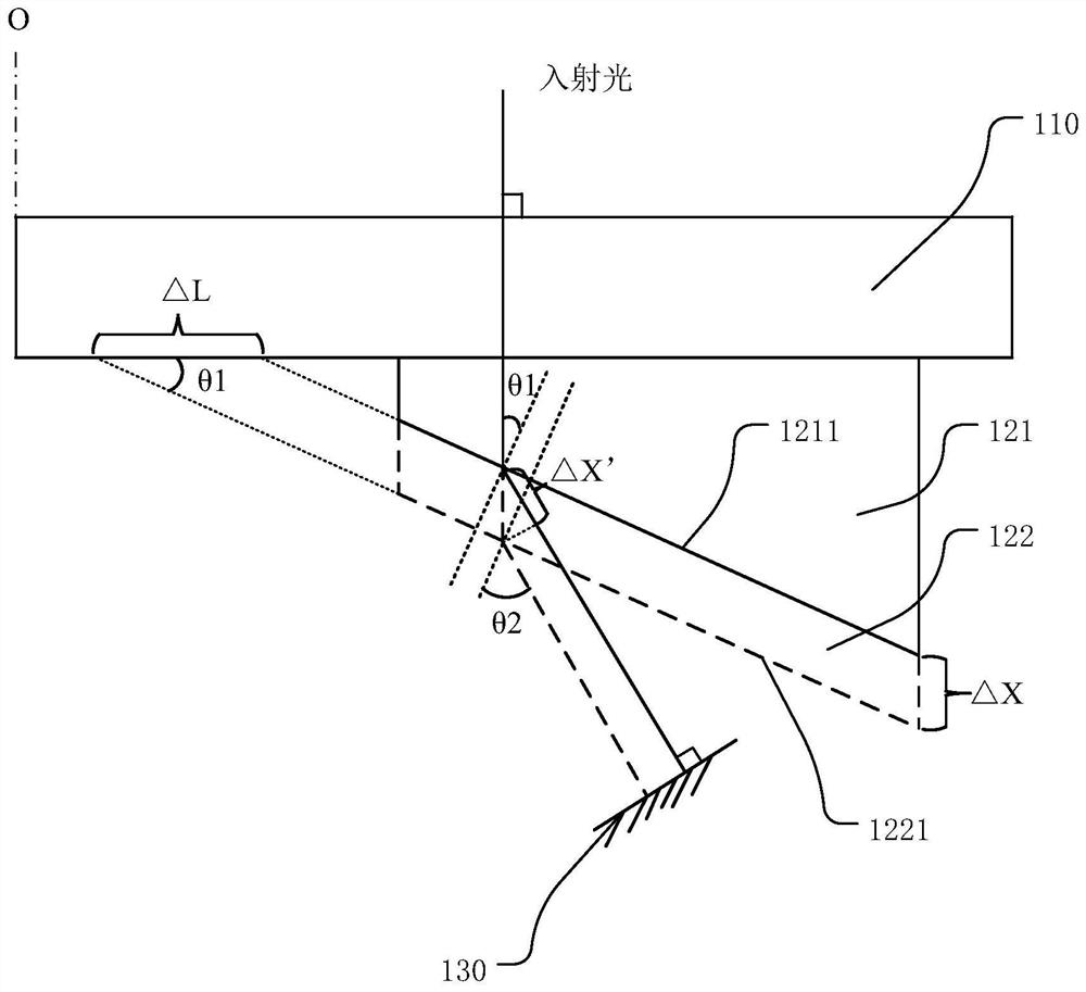
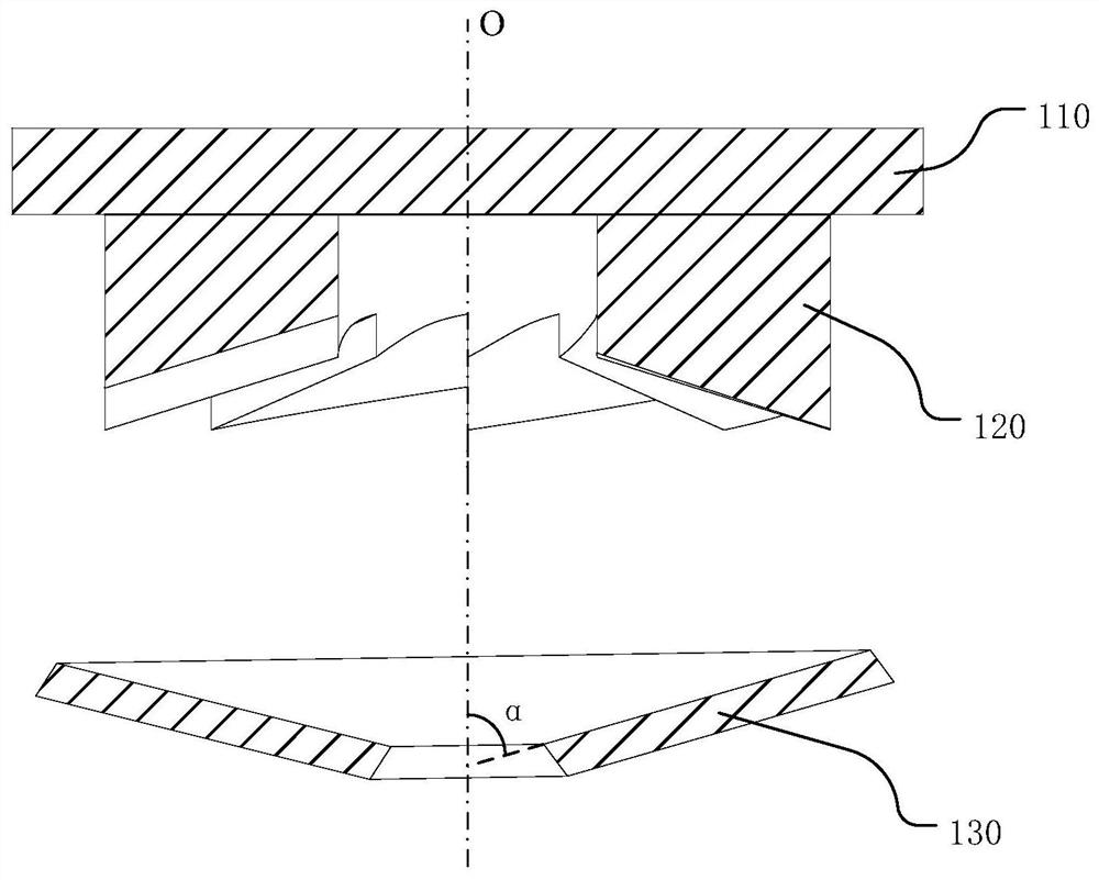
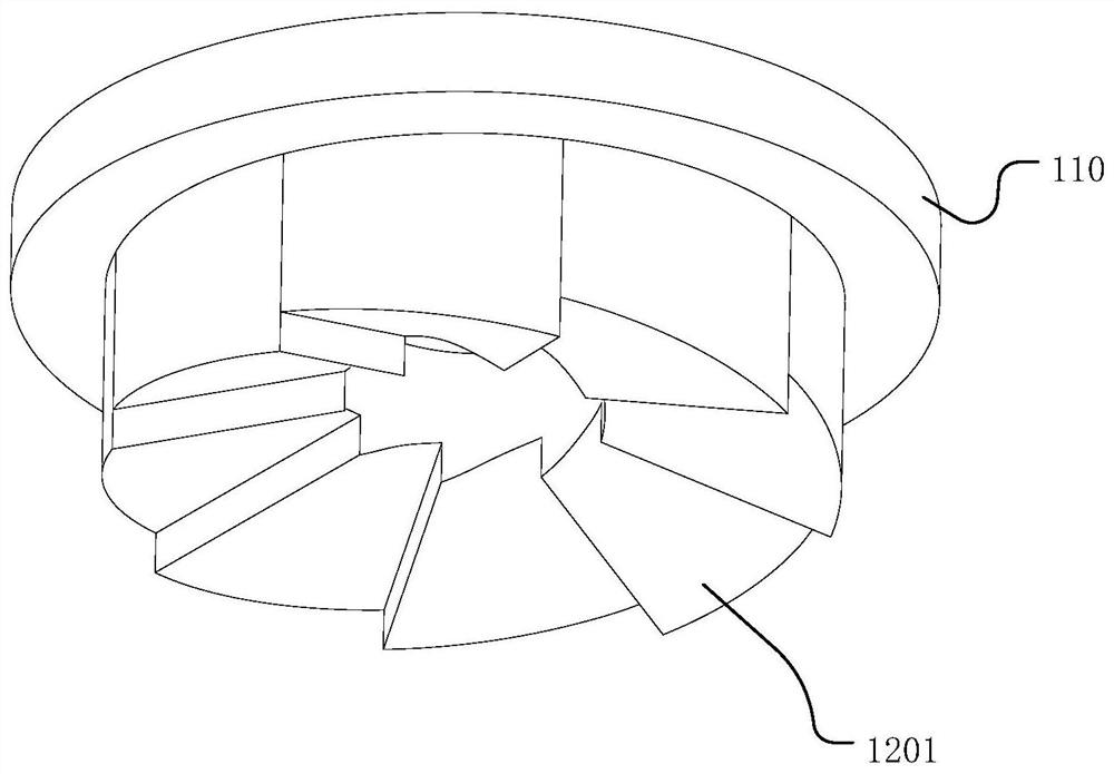
[0026] figure 1 The principle of the optical delay structure of the embodiment of the present invention is shown; figure 1 As shown, the optical delay structure includes: the turntable 110, the optical member 120, the mirror 130, wherein the turntable 110 is a uniform transparent medium disk having a refractive index of n, and the turntable 110 can rotate along the axis O, incident light. The incident point position is not changed, and the lower surface of the turntable 110 is provided with an optical member 120, in order to illustrate the principle of the optical delay structure, so figure 1 The first cross-section...


PUM


Abstract

The invention discloses an optical delay structure. The structure comprises a rotating disc which rotates along the central axis of the rotating disc, an optical component located on the lower surface of the rotating disc and connected with the rotating disc, and a reflecting mirror, wherein the optical component is in an annular shape; the reflecting mirror is located below the optical component, and the reflecting surface of the reflecting mirror is perpendicular to the light emitted from the optical component; the thickness of the optical component is changed along with the circumferential direction of the rotating disc, and incident light rays are emitted to the rotating disc from the upper surface of the rotating disc, pass through the optical component and then are emitted to the reflecting mirror from the emergent surface of the optical component; and the optical path of the incident light at the same incident position changes along with the change of the thickness of the optical component. By adopting the optical component with the thickness changing along the circumference, the required delay can be realized by the rotation of the rotating disc, and the scanning and detection of the pulse waveform to be detected by the ultra-short optical pulse can be further realized.

Description

Technical field [0001] The present invention relates to the field of optics, and more particularly to an optical delay structure. Background technique [0002] At present, in the field of optical detection, optical delay lines have a wide range of applications, such as the terahertz time domain spectroscopy, ultra-fast time resolution spectroscopy technology, optical coherence tomography technology, and optical pump detection techniques. [0003] In the terahertz time domain spectrum system and electro-optical sampling system, it is necessary to use variable optical delay means to change the relative delay between the two-way light, realize the scanning and detection of the ultra-short light pulse to measure the pulse waveform. Currently used optical delay means mainly have linear electric displacement stations, circular openings, fiber optic telescons, asynchronous optical sampling, etc., wherein linear electric displacement station is simple and easy to use, the scan length is ...

Claims


Application Information

Patent Timeline
IPC IPC(8): G02B26/08G01J1/42G01J11/00
CPCG02B26/0875G01J11/00G01J1/42G01J2001/4238
Inventor 胡晗齐静波
Owner UNIV OF ELECTRONIC SCI & TECH OF CHINA
Why Eureka
Try Eureka