
Trigger device for chain brake

A technology of triggering device and chainsaw, applied in chainsaws, manufacturing tools, wood processing appliances, etc., can solve problems such as injuries

Inactive Publication Date: 2005-06-15
HUSQVARNA AB
View PDF0 Cites 2 Cited by
  • Summary
  • Abstract
  • Description
  • Claims
  • Application Information

AI Technical Summary

Problems solved by technology

This support position results in the angle of the operator's arm no longer being significantly in line with the angle of the trigger arm, causing the trigger arm to scrape the arm against either light or hard contact, additionally, a long trigger in this design would The wire is left completely unprotected outside the saw, so there is a risk of injury

Method used


Image

  • Trigger device for chain brake
  • Trigger device for chain brake
  • Trigger device for chain brake

Examples


Embodiment Construction

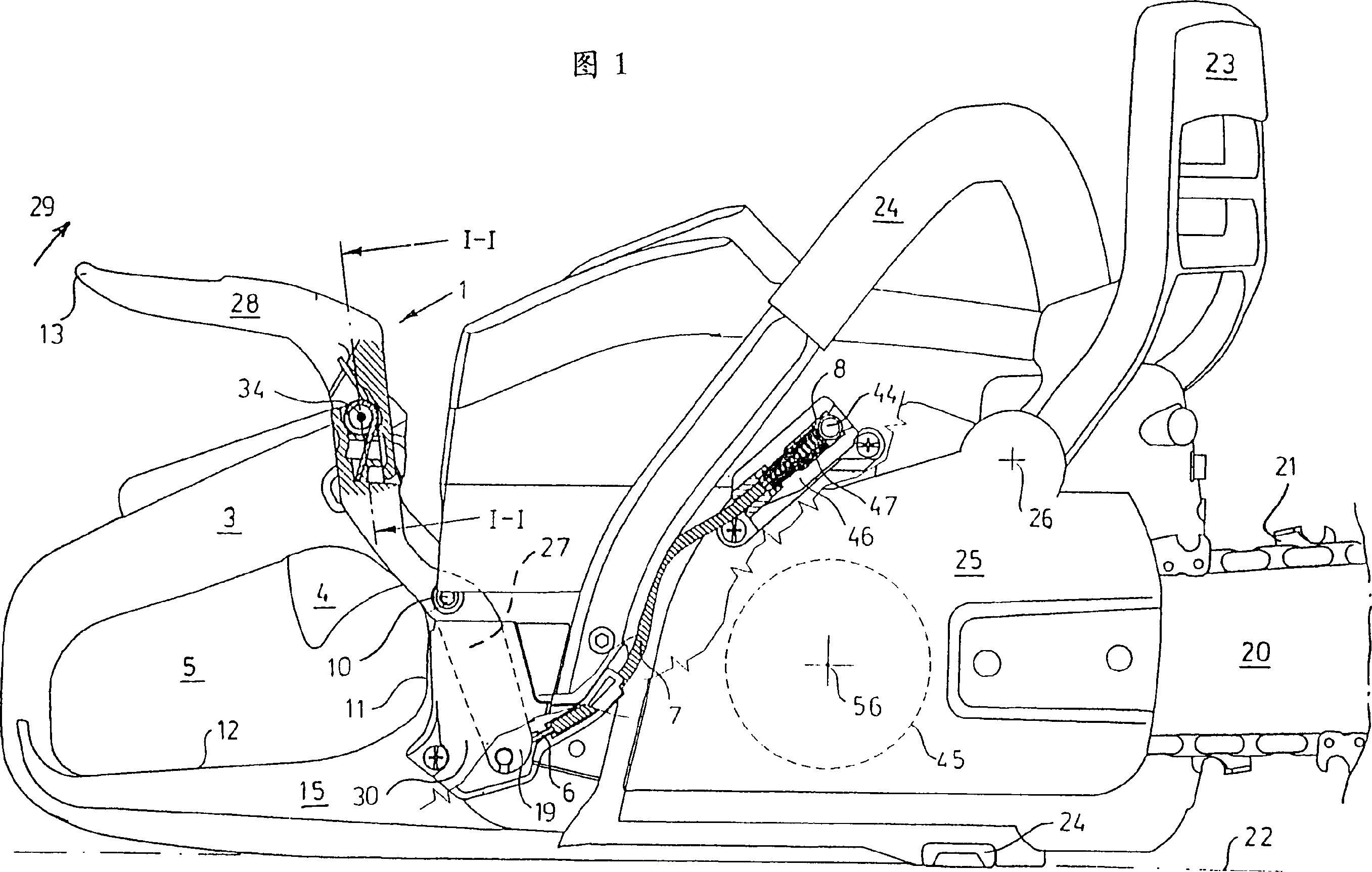
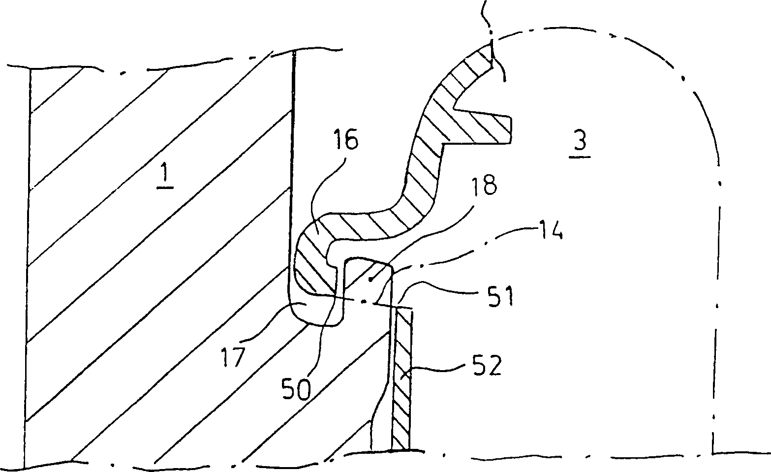
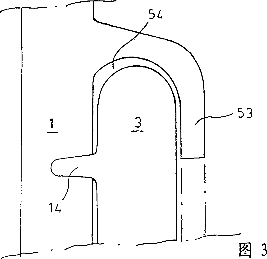
[0015] In the partial diagram 1 , numeral 2 designates a chainsaw or electric saw with a saw blade 20 and a saw chain 21 . In the following description, forward refers to the direction along the saw blade 20, and downward refers to the downward direction in the figure. For example, the saw is placed on the ground, where the ground is indicated by the numeral 22 . Said saw has a common handle frame 24 with a reverse rotation protection device 23 in front of the handle frame 24 . The saw has a rear handle 3 with a throttle control 4 and a handle opening 5 below the rear handle 3 . A clutch case 25 is provided with a braking device which is activated by turning the reverse rotation protection device 23 forward. The reverse rotation protection device 23 is pivotably mounted on the pivot shaft 26 . All of these are conventional and therefore need not be described in detail. The present invention is characterized in that the trigger arm 1 and the transmission mechanism 6, 7, 8, ...


PUM


Abstract

A brake triggering device with a pivotably mounted trigger arm (1) located in connection to a handheld working tool's, mainly a chain saw's (2), rear handle (3), with a throttle control (4) and a handle opening (5) located below the handle (3), so that the trigger arm (1), when the saw changes inclination in relation to the operator's forearm, e.g. at the event of kickback or fall, is actuated by the operator's hand or arm, whereby the trigger arm (1) via a transfer mechanism actuates a brake (9) so that this stops the movement of the saw chain. The pivot (10) of the trigger arm is located in connection to a front (11) or a bottom (12) side of the handle opening (5).

Description

technical field [0001] The invention relates to a brake trigger device with a trigger arm mounted in a hand-held working device, primarily a chain saw, comprising a rear handle with a yoke control and a The handle opening below the handle makes it possible for the trigger arm to be activated by the operator's hand or arm when the saw changes inclination due to the operator's forearm, i. The operation of the saw chain is braked. Background technique [0002] There are several serious accident hazards when using a chain saw. So-called reverse accidents can occur, that is, the saw blade with the rotating saw chain swings towards the operator of the saw. Fall accidents can occur when the operator slips or falls onto a saw with a rotating saw chain. In order to reduce the risk of reverse rotation injuries, chain saws are usually equipped with a chain brake which is activated by a so-called reverse rotation protection device. The chain brake is mounted on the front handle of t...

Claims


Application Information

Patent Timeline
Patent Type & Authority Patents(China)
IPC IPC(8): B27B19/00B27B17/00B27B17/08
CPCB27B17/083
Inventor 彼得·比约克曼佩尔·马丁松
Owner HUSQVARNA AB
Learn More