Reflection type optical valve projection system

A reflective, light valve technology, applied in optics, optical components, instruments, etc., can solve problems such as uneven contrast, reduced brightness output of optical systems, and loss of polar beam conversion

Inactive Publication Date: 2005-06-01
YOUNG OPTICS +1
View PDF0 Cites 0 Cited by
  • Summary
  • Abstract
  • Description
  • Claims
  • Application Information

AI Technical Summary

Problems solved by technology

[0004] Due to the angular dependence of the traditional polar polarizer, that is, for the beams (skew rays) incident at various oblique angles, the traditional polar polarizer will produce beams with different polarities due to different directions, resulting in some The loss of polar beam conversion, resulting in severe contrast unevenness and low contrast
Therefore, when the components of the existing imaging system 10 are configured, it will be limited by the polarization angle characteristic distribution of the polarity separation coating 113 relative to the incident illumination beam and light valve reflected light. / # larger) optical system, thus reducing the light output of the optical system

Method used


Image

  • Reflection type optical valve projection system
  • Reflection type optical valve projection system
  • Reflection type optical valve projection system

Examples


Embodiment Construction

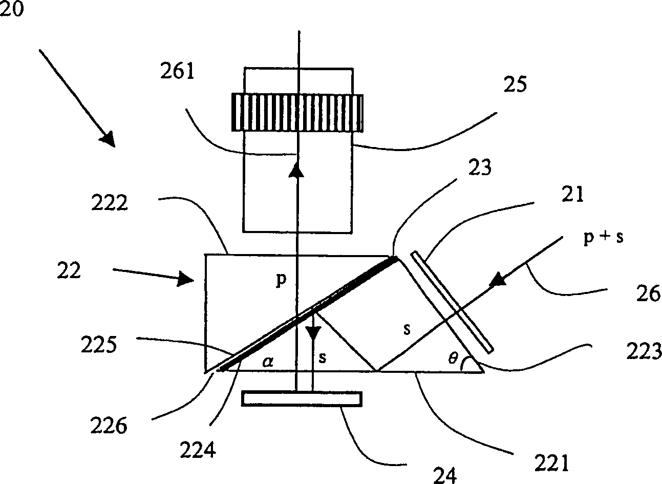
[0016] see figure 2 , is the imaging system 20 according to the first embodiment of the present invention, including a polarizer 21 , a prism module 22 with a wire-grid polarizer 23 (Wire-Grid Polarizer), a reflective light valve 24 and a lens group 25 . The illumination beam 26 is polarized into a desired polar beam mainly through the polarizer 21 and the wire grid polarizer 23, which is incident on the reflective light valve 24, and then reflected to the lens group 25 to form an image.

[0017] Wherein, the prism module 22 of the imaging system 20 is a cylindrical prism with two substantially parallel outer surfaces 221 and 222, one side surface 223 is not parallel to the outer surfaces 221 and 222, and the prism module 22 has two outer surfaces 221 and 222 in the interior. 222. The tangent planes 224 and 225 of the two diagonal sides are substantially parallel to each other, and are separated by a small gap 226. A metal wire grid polarizer 23 is arranged on the tangent pla...


PUM


Abstract

A reflective light valve imaging system, including a prism module, which contains two outer surfaces and one side surface, and the interior has two inclined adjacent cut surfaces between the two outer surfaces; a metal wire grid polarizer is arranged on the side A tangent surface of the surface; a reflective light valve is arranged near the outer surface next to the metal wire grid polarizer; and a lens group is arranged near the other outer surface. The polarized light beam is pre-polarized by the polarizer to form the required polar light beam, so that the uniform polarized light beam enters the prism module, and then enters the metal wire grid polarizer after total reflection, and is completely reflected by the metal wire grid polarizer at various incident angles The polar light beam is irradiated to the reflective light valve, modulated by the light valve and then projected to the lens group to form an image. The invention can avoid the polarization separation loss of oblique incidence, increase the contrast of the system image, and make the spatial configuration of the imaging system more flexible.

Description

technical field [0001] The invention relates to a display system, in particular to a reflection type light valve display system using a prism module. Background technique [0002] In order to meet the requirements of the light valve for a specific polar beam, the existing imaging system forms the illumination beam into a single polar beam in advance, and then irradiates the light valve with a single polar illumination beam to improve the quality of the image. [0003] like figure 1 As shown, the prior art imaging system 10 uses a polarizing beamsplitter (PBS) as a means of polarizing the illuminating light beam. The polarizing beamsplitter 11 consists of two right-angled cylindrical prisms 111 and 112 which are mutually adhered by the hypotenuses. The junction forms a prism with a square cross section, and a polarization splitting coating 113 is provided on the surface of the bonding hypotenuse, and the polarized beam is polarized by selectively reflecting the characteristi...

Claims


Application Information

Patent Timeline
Patent Type & Authority Patents(China)
IPC IPC(8): G02B5/06G02B27/18G02B27/28
Inventor 吕和
Owner YOUNG OPTICS
Why Eureka
Try Eureka