Sewing machine

A technology for sewing machines and sewing needles, which is applied in the direction of sewing machine components, needle holders for sewing machines, sewing equipment, etc., and can solve problems such as difficulties and complicated replacement operations of needle clamp parts 3

Inactive Publication Date: 2005-05-04
YAMATO SEWING MASCH MFG CO LTD
View PDF0 Cites 1 Cited by
  • Summary
  • Abstract
  • Description
  • Claims
  • Application Information

AI Technical Summary

Problems solved by technology

At this time, it is more difficult to embed the front end of the screwdriver inserted from the through hole 13 into the screw head groove of the fixed threaded part 19.
This also makes the replacement operation of the needle clip part 3 complicated

Method used


Image

  • Sewing machine
  • Sewing machine
  • Sewing machine

Examples


Embodiment Construction

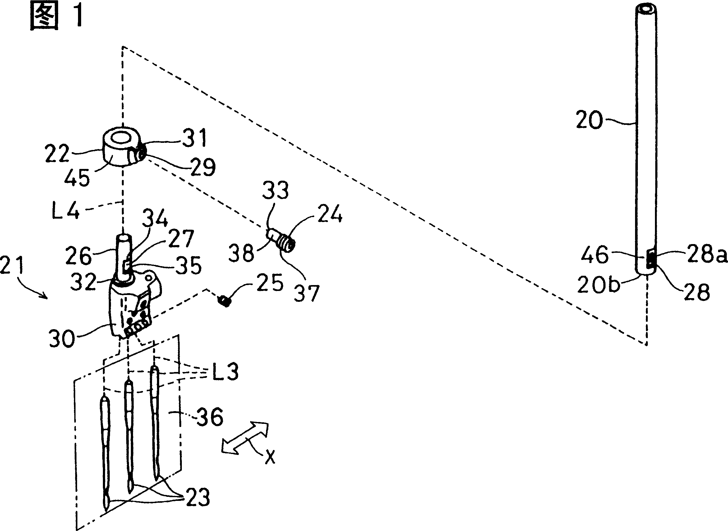
[0044] Refer to Figure 1 to Figure 5 A first embodiment of the present invention will be described. And in the sewing machine of the present invention, the structures other than the connecting portion of the needle bar and the needle clamp member are different from those in the Figure 12 It is the same as the past flat chain sewing machine 1 explained in Fig. 15, and Figure 12 The drawing descriptions related to each drawing of FIG. 15 are used in the first embodiment here.

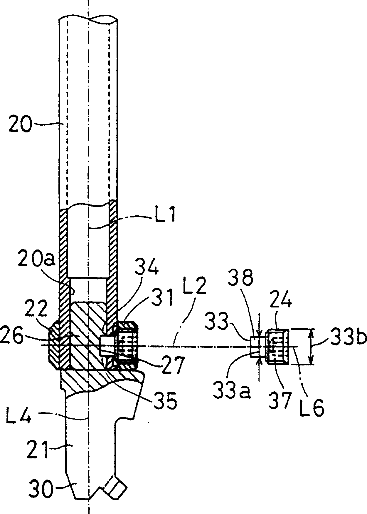
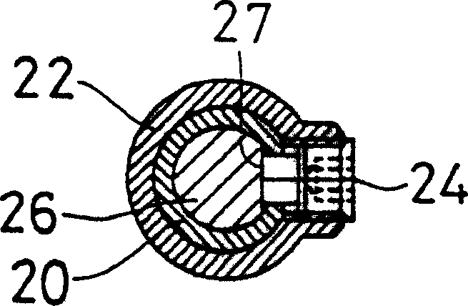
[0045] Fig. 1 shows the exploded perspective view of the needle bar 20 and the needle clip part 21 of the present embodiment, figure 2 A longitudinal sectional view showing the connecting portion of the needle bar 20 and the needle clamp member 21, image 3 Representing the cross-sectional view of the connecting portion of the needle bar 20 and the needle clamp member 21 at right angles to the axis, Figure 4 express figure 2 An enlarged cross-sectional view of a part of Figure 5 Indicated by ...


PUM


Abstract

The present invention provides a sewing machine, in which the necessary adjustment of the height of the needle bar and the adjustment of the position of the staggered hole relative to the needle lifter can be simply performed or unnecessary during the operation of replacing the needle clamp part, so that the needle clamp part can be easily adjusted. replace. The needle bar 20 is hollow, and the lower end is provided with a threaded through hole 28a. A radial screw hole 29 is formed in the positioning member 22 attached to the lower end of the needle bar 20 . An insertion shaft 26 extending parallel to the sewing needle 23 is formed on the upper portion of the needle clamp member 21 . The sides of the insertion shaft 26 form flat surfaces 27 . When installing the needle clamp member 21, first install the positioning member 22 on the lower end of the needle bar 20, insert the insertion shaft 26 of the needle clamp member 21 from the lower end of the needle bar, and screw the needle clamp to the threaded hole 29 of the positioning member 22 to fix it. Threaded part 24 . The front end surface 33 of the needle clip fixing screw member 24 is in contact with the flat surface 27 of the insertion shaft 26 of the needle clip member 21 so as to be positioned at the axial circumferential position of the needle clip member 21 .

Description

technical field [0001] The present invention relates to a sewing machine which can replace a needle clip part for fixing a sewing needle. Background technique [0002] Figure 12 It is a perspective view showing the structure around the sewing needle of the conventional flat chain stitch sewing machine 1 . The flat chain stitch sewing machine 1 is horizontally equipped with a needle jack 5 on the sewing machine base plate 6 , and is provided with a plurality of needle jacks 5 , here are 3 sewing needles 4 . The sewing needle 4 is fixed on the needle clamp part 3, and the needle clamp part 3 is fixed on the lower end of the vertically arranged needle bar 2. The top of the needle bar 2 is connected with the crankshaft 66 (referring to Fig. 14), and the rotation of the crankshaft 66 makes the needle bar 2 reciprocate in the up and down direction, and the sewing needle 4 is inserted in the wrong foot hole 9 of the needle jack plate 5. A pressing member (not shown) for pressing...

Claims


Application Information

Patent Timeline
Patent Type & Authority Patents(China)
IPC IPC(8): D05B55/02D05B1/10D05B55/10
Inventor 水崎隆丸山隆
Owner YAMATO SEWING MASCH MFG CO LTD
Why Eureka
Try Eureka