Eureka AIR delivers breakthrough ideas for toughest innovation challenges, trusted by R&D personnel around the world.

Lift controller

A technology of an elevator control device and an electric energy storage device, which is applied in the direction of circuit devices, battery circuit devices, control systems, etc., can solve the problems of reducing the peak power consumption of power demand, reducing power consumption, etc., and achieving the goal of reducing the use of city power Effect

Inactive Publication Date: 2005-04-20
MITSUBISHI ELECTRIC CORP
View PDF0 Cites 8 Cited by
  • Summary
  • Abstract
  • Description
  • Claims
  • Application Information

AI Technical Summary

Problems solved by technology

For example, in the hot summer afternoon, the power demand reaches its peak. It is hoped to reduce the power consumption during this time period, but the existing elevator control device cannot sufficiently reduce the power consumption during the peak power demand.
[0009] In this way, the conventional elevator control device consumes power synchronously with the operation of the elevator, so the power consumption cannot be reduced during peak power demand.

Method used


Image

  • Lift controller
  • Lift controller
  • Lift controller

Examples


Embodiment Construction

[0022] Embodiment 1

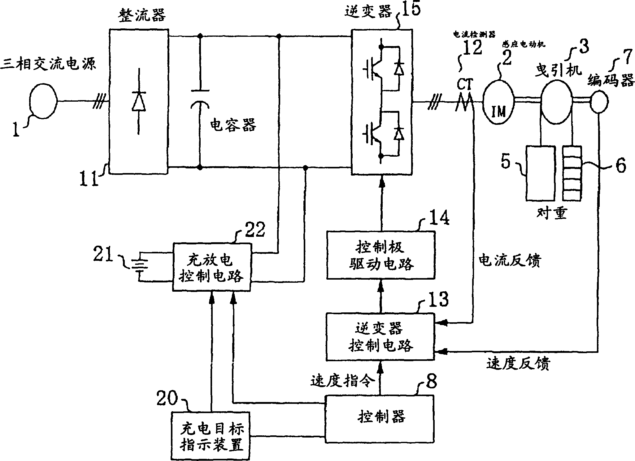
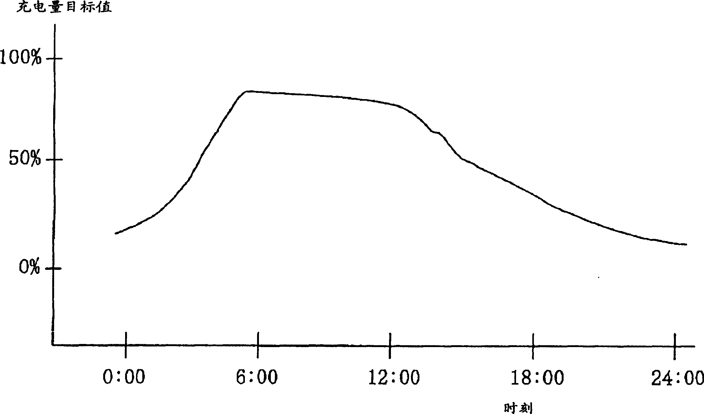
[0023] Use below figure 1 One embodiment of the elevator control device of the present invention will be described. figure 1 It is a block diagram of the elevator control apparatus of this embodiment. in the figure 1 Among them, 20 is a charging target indicating device, which is composed of a common microprocessor and a program, and is connected to the controller 8 . The charging target value is set by the charging target indicating device 20 . 21 is an electric energy storage device, which is composed of a battery or the like.

[0024] 22 is a charging and discharging control circuit, which is composed of a DC / DC converter and the like. The charging and discharging control circuit 22 is connected to the charging target indicating device 20 , the electric energy storage device 21 , and the bus between the rectifier 11 and the inverter 15 .

[0025] Also, the charging and discharging control circuit 22 receives the charging target value output fr...


PUM


Abstract

The present invention relates to elevator controls. The conventional elevator control device consumes electric power in synchronization with the operation of the elevator, and thus cannot reduce electric power consumption at the peak time of electric power demand. The elevator control device of the present invention includes a rectifier for rectifying and converting alternating current into direct current, an inverter for converting the direct current into alternating current with variable voltage and variable frequency, and using the alternating current with variable voltage and variable frequency to drive the elevator to run. The electric motor of the present invention is characterized in that the elevator control device further includes a chargeable electric energy storage device, and a charge and discharge control means for controlling the charge and discharge of the electric energy storage device according to the hourly charge target value of the electric energy storage device.

Description

technical field [0001] The invention relates to elevator controls using electrical energy storage devices. Background technique [0002] Figure 5 Indicates an existing elevator control device. Should Figure 5 It is a structural diagram of an existing elevator control device. in the Figure 5 Among them, 1 is a power frequency AC power supply (hereinafter referred to as "mains"), 2 is an electric motor such as an induction motor, 3 is a traction machine, 4 is a traction wire rope, 5 is an elevator car, and 6 is a counterweight. Driving the traction machine 3 to rotate can make the elevator car 5 and the counterweight 6 connected to the two ends of the traction wire rope 4 go up and down, and the passengers in the car are transported to a predetermined floor. [0003] 8 is a controller, which determines the start and stop of the elevator, and generates its position and speed commands at the same time. 11 is a rectifier, which consists of a diode etc. The rectifier 11 rec...

Claims


Application Information

Patent Timeline
Patent Type & Authority Patents(China)
IPC IPC(8): B66B1/06B66B1/30B66B1/34H02J3/32
CPCB66B1/302H02J3/32B66B1/308B66B1/06
Inventor 田岛仁荒木博司菅郁朗小林和幸
Owner MITSUBISHI ELECTRIC CORP
Why Eureka
Eureka Blog
Learn More