Front end module of mobile communication device

A front-end module and communication system technology, applied in the direction of multiplexing communication, multi-terminal pair network, printed circuit connected with non-printed electrical components, etc., can solve the problem of damage to productivity, complexity of multi-layer substrate design, and circuit interference And other issues

Inactive Publication Date: 2004-12-15
TDK CORPARATION
View PDF1 Cites 0 Cited by
  • Summary
  • Abstract
  • Description
  • Claims
  • Application Information

AI Technical Summary

Problems solved by technology

This complicates the design of multilayer substrates, and easily causes interference between circuits and deformation during lamination and sintering processes, thus impairing productivity

Method used


Image

  • Front end module of mobile communication device
  • Front end module of mobile communication device
  • Front end module of mobile communication device

Examples


Embodiment Construction

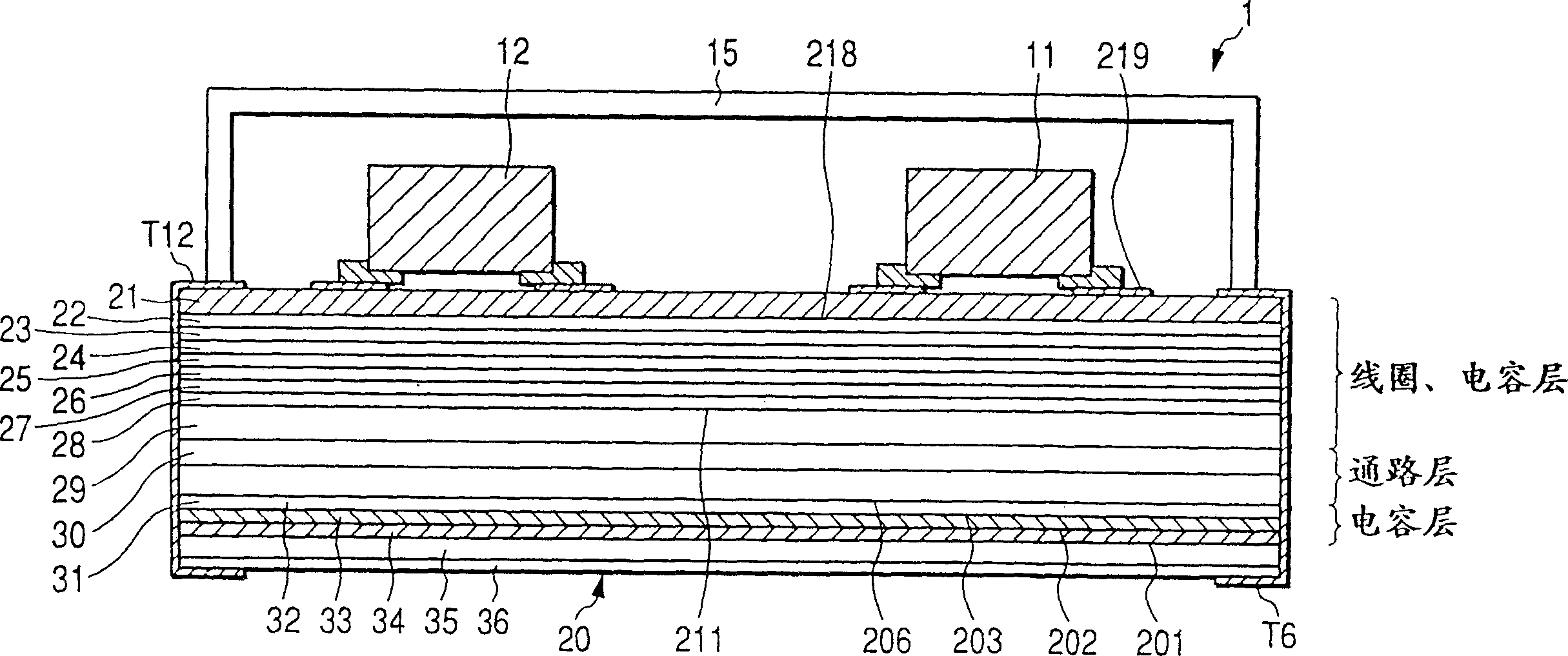
[0023] Embodiments of the present invention will be described below with reference to the drawings. figure 1 is a cross-sectional view showing the front-end module. The front-end module 1 mounts surface-mounted components 11 , 12 on a multilayer substrate 20 . The shielding case 15 is fixed on the multilayer substrate 20 so as to cover the multilayer substrate 20 and the surface mount components 11 , 12 .

[0024] The multilayer substrate 20 includes dielectric layers 21 to 36 . figure 1 Each of the dielectric layers 21 to 36 is shown in a thickness corresponding to its actual thickness.

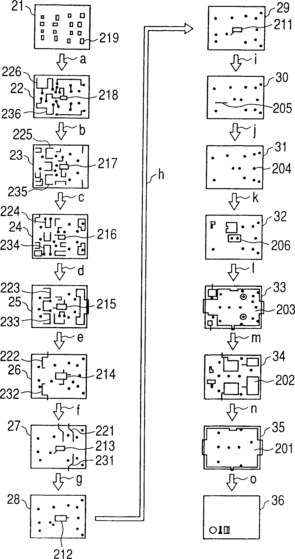
[0025] figure 2 Shows the layer structure of the front-end module. The front-end module stacks dielectric green sheets on which electrodes, wiring patterns, via holes, or marks corresponding to a large number of front-end modules are provided in the vertical and horizontal directions, and the dielectric green sheets are cut into individual front-end modules. Module material, green shee...


PUM


Abstract

The front-end module is composed of a multilayer substrate and surface-mounted components. The front end module constitutes antenna switches, filters, and a high frequency circuit comprising a band splitter circuit as well as the front end of the transceiver circuit equipped with a plurality of transmission / reception features whose communications systems are different. The multilayer substrate arranges a band splitter circuit pattern at the center in the plane direction and symmetrically arranges a plurality of antenna switch conductor patterns whose communications systems are different, with respect to the pattern for the band splitter circuit.

Description

technical field [0001] The present invention relates to a front-end module having an antenna switch as a key element used in mobile communication devices such as mobile phones and car phones. Background technique [0002] An antenna switch disclosed in Japanese Patent Laid-Open No. 9-261110 / (1997) filed by the applicant of the present invention is an example of a conventional front-end module of a mobile communication device. Most mobile phones transmit and receive on different frequency bands. Therefore, although such circuits are similar to each other, element constants of such mobile phone systems tend to differ between the transmit / receive selector and the antenna selector. In order to avoid defects in quick design, the antenna switch described in Japanese Patent Laid-Open No. 9-261110 / (1997) has a selector circuit in which one of the transmit / receive selector and the antenna selector is connected to the other The selector is symmetrical with respect to the low pass fi...

Claims


Application Information

Patent Timeline
IPC IPC(8): H04B1/44H03H7/46H04B1/52H05K1/02H05K1/03H05K1/16H05K1/18
CPCH05K1/181H05K1/16H04B1/52H05K1/0306H05K1/0237H03H7/46H04B1/44
Inventor 原田畅巳须贺诚志多多纳宏长谷川英树
Owner TDK CORPARATION
Why Eureka
Try Eureka