Process for preparing isolating wall of plasma display

A plasma and manufacturing method technology, applied in the manufacture of discharge tubes/lamps, cold cathodes, electrode systems, etc., can solve the problem that the uniformity of width and contour is difficult to control, affects the efficiency of discharge cells, and affects the good rate of products, etc. problem, to achieve the effect of more consistent efficiency, improved efficiency, and increased discharge space

Inactive Publication Date: 2004-12-15
AU OPTRONICS CORP
View PDF0 Cites 0 Cited by
  • Summary
  • Abstract
  • Description
  • Claims
  • Application Information

AI Technical Summary

Problems solved by technology

[0006] In the manufacturing process of the above-mentioned traditional barrier rib 18a, although the dielectric layer 14 below the barrier rib 18a can protect the addressing electrode 12 from being damaged during the sandblasting process, but in order to manufacture the dielectric layer 14, it is necessary to add a High temperature sintering step, thus affecting the good rate of the product
In addition, since the height of the barrier wall 18a is about 100-200 microns, the sandblasting time required to remove unnecessary barrier material with sand is very long, so it is often difficult to uniform the width and profile of the bottom of the barrier wall 18a control, while affecting the efficiency of each discharge cell

Method used


Image

  • Process for preparing isolating wall of plasma display
  • Process for preparing isolating wall of plasma display
  • Process for preparing isolating wall of plasma display

Examples


Embodiment Construction

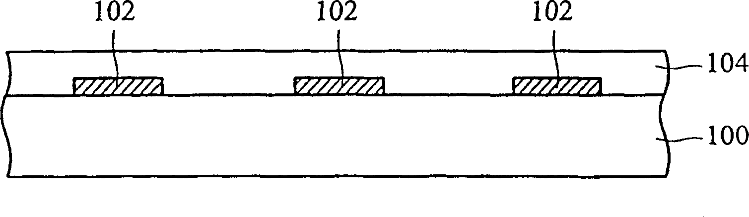
[0024] The following will match Figure 2A to Figure 2G , the method for manufacturing the barrier rib of the present invention will be described in detail.

[0025] First please refer to Figure 2A , forming a plurality of address electrodes 102 on the rear glass substrate 100 . Afterwards, a dielectric layer 104 is covered on the address electrodes 102 to protect the electrodes. Its forming method can be printing method. It should be noted that the dielectric layer 104 has not yet been sintered.

[0026] Then please refer to Figure 2B , at this time, the dielectric layer does not need to be subjected to a high-temperature sintering process, and a layer of photosensitive dry film (photosensitive dry film) 106 is directly formed on the dielectric layer 104. The preferred type is a negative photoresist, and its thickness should be as thick as possible. Thin, about 5 to 30 microns. The photosensitive dry film 106 can be formed by a laminate method.

[0027] Then please r...


PUM


Abstract

A process for preparing the barrier wall of plasma display includes such steps as first generating a number of electrodes at predefined positions on glass substrate, and forming a dielectric layer on each of them, generating several sand blast terminating layers on the dielectric layers corresponding to the said electrodes, and after coating a layer of isolating material, generating a sand resistant layer, sand blasting until the sand blast terminating layer is exposed to form several barrier walls, removing sand resistant layer and sand blast terminating layer, and sintering.

Description

technical field [0001] The present invention relates to a plasma display (plasma display panel; PDP), in particular to a method for manufacturing a barrier wall (rib) of the PDP. Background technique [0002] The plasma display is a flat panel display (FPD) that emits light through gas discharge, and its main features are light, thin, easy to enlarge, and has no viewing angle problem. [0003] Generally, a plasma display is composed of a front panel (front panel) and a rear panel (rear panel). The barrier wall of the plasma display is formed on the rear panel as the interval of the discharge space to define a small discharge space. , and prevent the mixing of RGB three-color phosphors. Below, refer to Figure 1A to Figure 1B , introduces the conventional fabrication method of the barrier rib. [0004] First, please refer to Figure 1A After an address electrode (address electrode) 12 is formed on the surface of the rear glass substrate 10, a dielectric layer 14 is covered...

Claims


Application Information

Patent Timeline
Patent Type & Authority Patents(China)
IPC IPC(8): H01J9/00H01J11/36H01J17/49
Inventor 许国彬
Owner AU OPTRONICS CORP
Why Eureka
Try Eureka