Air cylinder device for artificial limb
A cylinder device and prosthesis technology, which is applied in the field of bending to generate appropriate resistance, can solve problems such as poor walking feeling of the prosthetic device installer
- Summary
- Abstract
- Description
- Claims
- Application Information
AI Technical Summary
Problems solved by technology
Method used
Image
Examples
no. 1 Embodiment
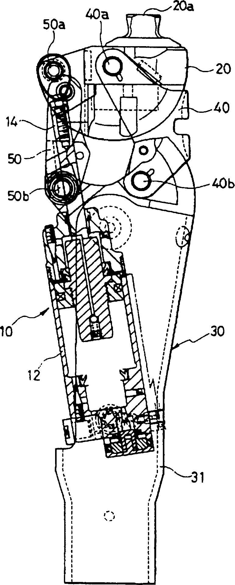
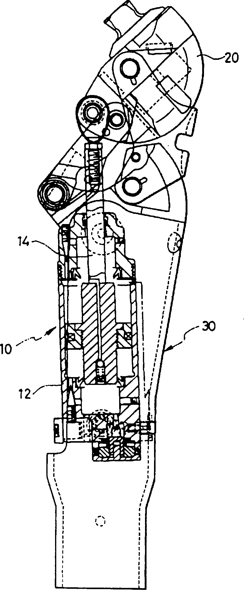
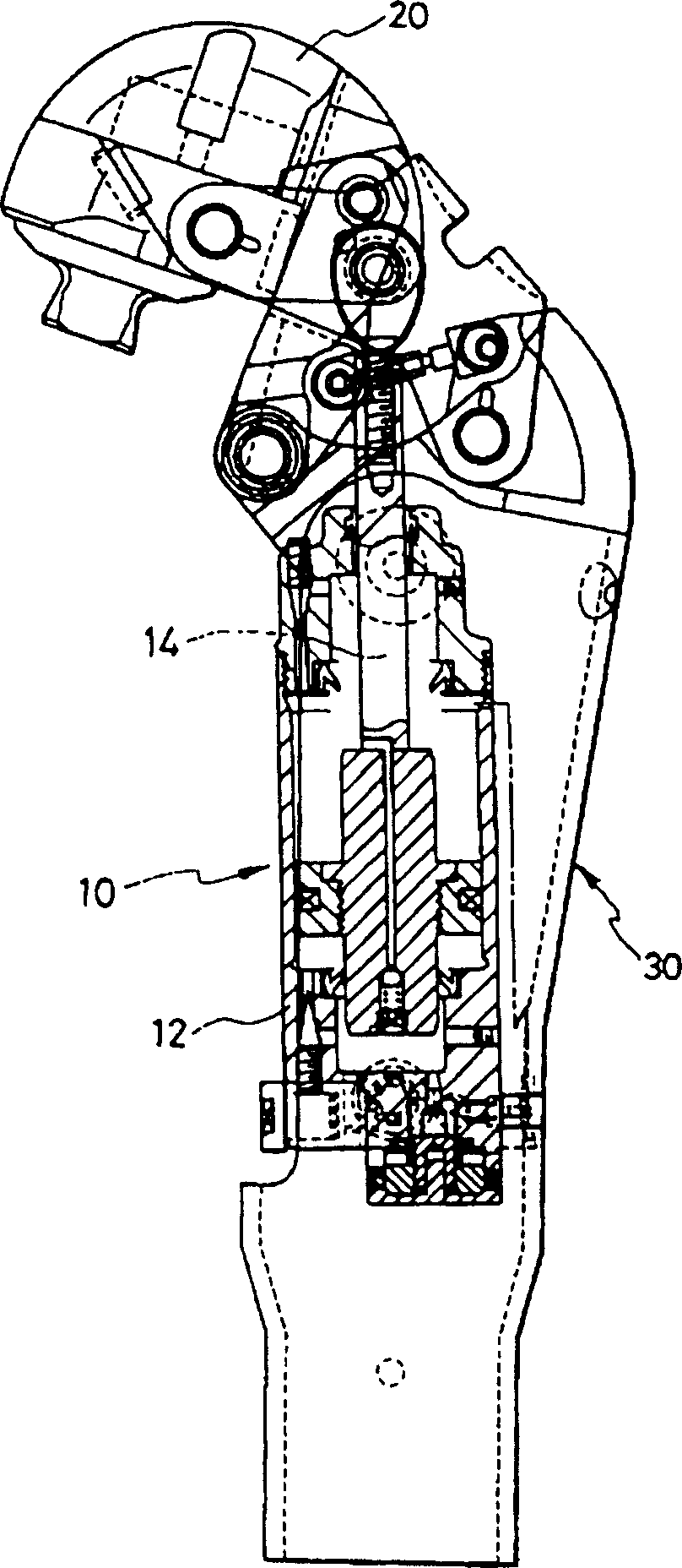
[0039] Figure 7-9 A cylinder device 110 according to a first embodiment of the present invention is shown. In these figures, each figure is consistent with the preceding Figure 1~3 or Figure 4~6 Same, as one of the graph's Figure 7 Represents the state where the knee is extended and the bending angle is zero, as another figure Figure 8 Indicates that the knee is in a slightly bent state, as the rest of the figure Figure 9 Indicates that the knee is in a state of maximum flexion. Also for other embodiments shown later, these three states are represented by drawings respectively.
[0040] The cylinder device 110 includes a cylindrical cylinder body 112 formed of aluminum alloy or synthetic resin. The cylinder main body 112 includes a cylinder liner 112c whose inner diameter is uniform, and a cover portion 112h and a cylinder tube portion 112b that are located at respective ends of the cylinder liner 112c and close the respective ends. Since parts such as a piston ar...
no. 2 Embodiment
[0049] Figures 11 to 13 A cylinder device 2110 according to a second embodiment of the present invention is shown. In this air cylinder device 2110 , a concave portion 2127 is provided on the side of the piston 2113 of the cylinder body 2112 , and a convex portion 2140 fitted into the concave portion 2127 is provided on the side of the cylinder portion 2112b of the cylinder body 2112 . Correspondingly, the first passage 2101 including the first check valve 91 allowing the flow from the first chamber 81 toward the second chamber 82 is provided on the side of the cylinder liner 2112c in the same way as the second passage 2102 which is another communicating passage. in the wall. Also in the cylinder device 2110 of the second embodiment, as in the case of the first embodiment, the throttle valve 140 usually raises the pressure on the side of the second chamber 82 at the stage where the knee bending angle is small, but when it is at a predetermined stage, the second chamber 82 i...
no. 3 Embodiment
[0051] Figures 14 to 16 A cylinder device 3110 according to a third embodiment of the present invention is shown. This cylinder device 3110 has something in common with the case of the second embodiment in that the concave portion 3127 on the side of the piston 3113 and the convex portion 3140 on the side of the cylinder portion 3112b of the cylinder body 3112 are fitted together, and the first passage 3101 and the second passage 3102 is located in the sidewall of cylinder liner 3112c. This embodiment differs from the second embodiment in that the chambers divided by the partition are reversed, and the chamber 3822 newly divided by the partition is located inside the concave portion 3127 of the piston 3113 . Then, the pressure of the newly divided chamber 3822 is increased by the throttle valve 824 , and the pressure of the chamber 3821 on the side periphery of the convex portion 3140 is increased by the throttle valve 140 in normal times. In addition, since the chambers di...
PUM
 Abstract
Description
Claims
Application Information
 - R&D
- Intellectual Property
- Life Sciences
- Materials
- Tech Scout
- Unparalleled Data Quality
- Higher Quality Content
- 60% Fewer Hallucinations
Browse by: Latest US Patents, China's latest patents, Technical Efficacy Thesaurus, Application Domain, Technology Topic, Popular Technical Reports.
© 2025 PatSnap. All rights reserved.Legal|Privacy policy|Modern Slavery Act Transparency Statement|Sitemap|About US| Contact US: help@patsnap.com


