
Debris collection device and method

一种收集装置、碎屑的技术,应用在垃圾收集、维护和安全配件、应用等方向,能够解决提高成本、增加装置复杂性等问题

Inactive Publication Date: 2004-11-03
DUSTBUBBLE
View PDF1 Cites 0 Cited by
  • Summary
  • Abstract
  • Description
  • Claims
  • Application Information

AI Technical Summary

Problems solved by technology

However, using a combination of these components and since some of them are detachable and replaceable increases the complexity and cost of the device

Method used


Image

  • Debris collection device and method
  • Debris collection device and method
  • Debris collection device and method

Examples


Embodiment Construction

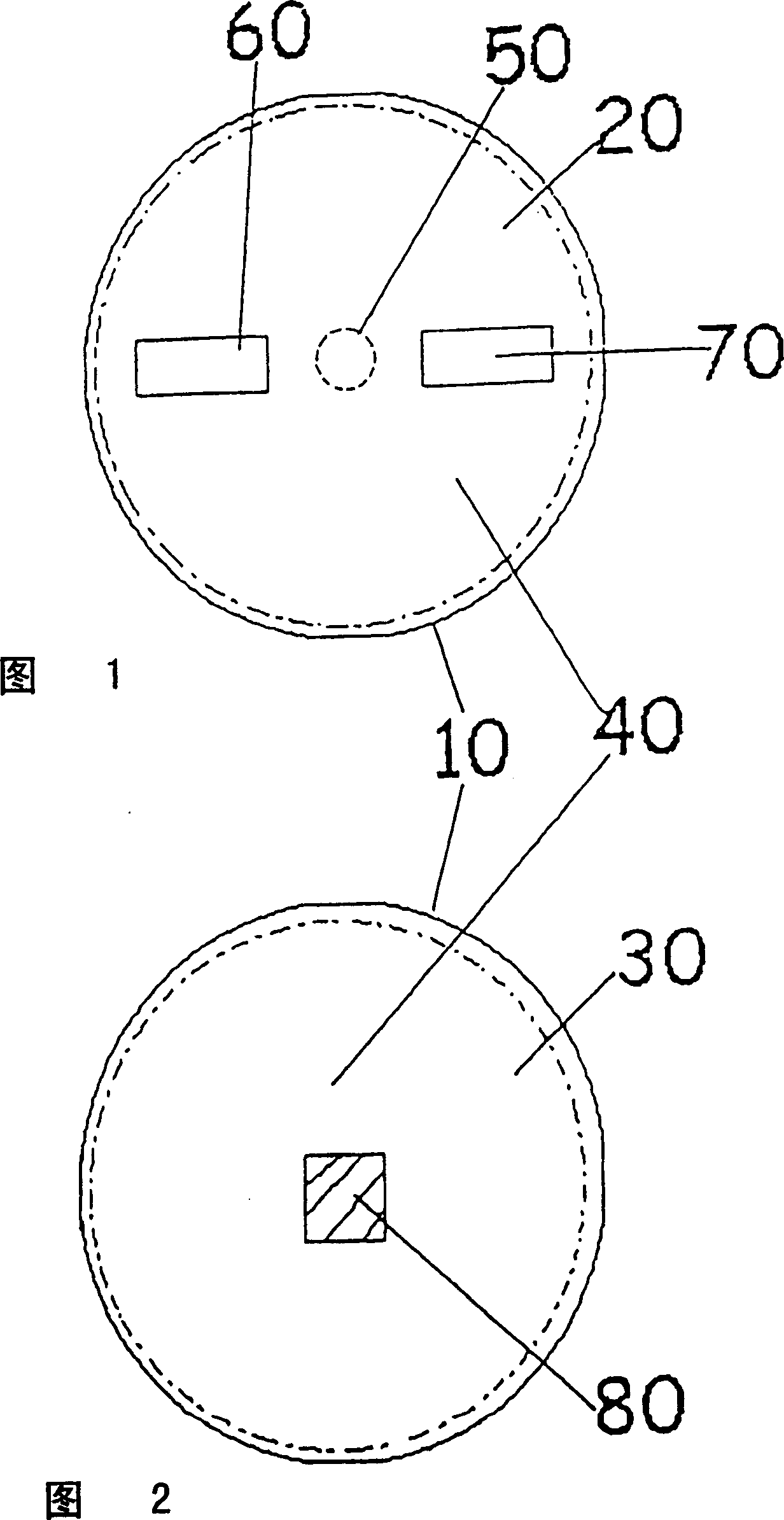
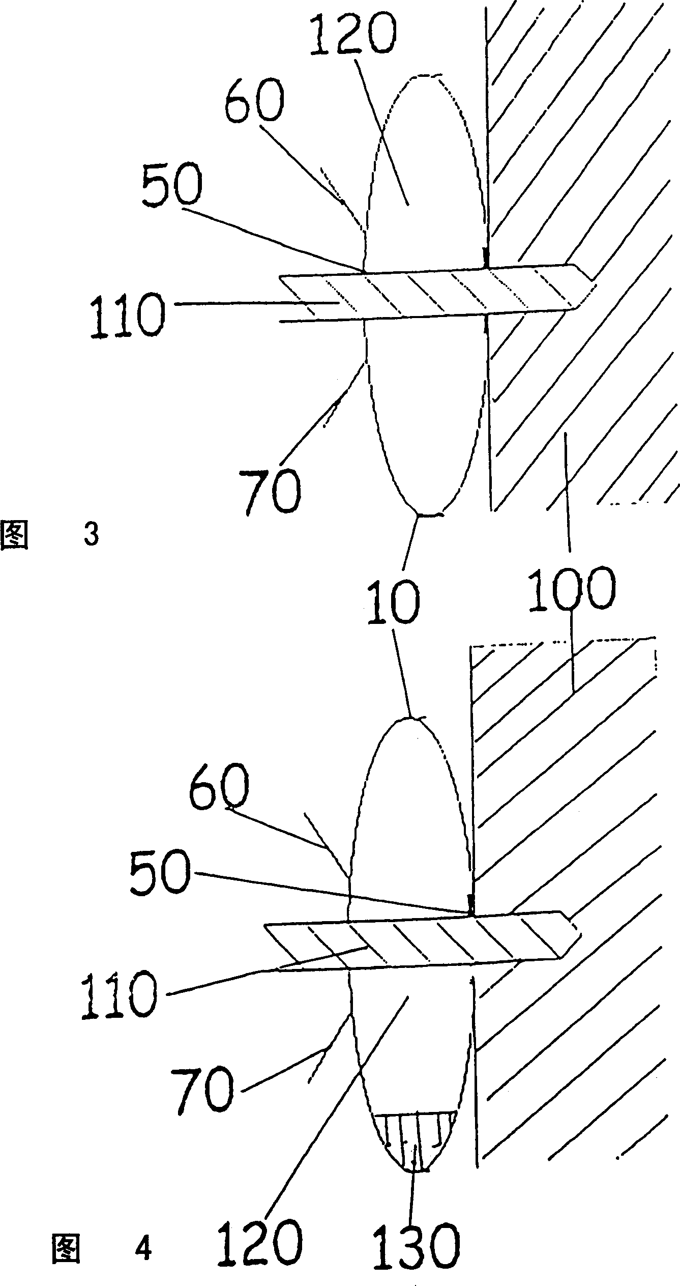
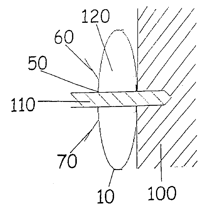
[0019] Fig. 1 and Fig. 2 are respectively the front view and the rear view of the collecting device involved in the present invention. The collecting device comprises a body 10 having a front surface 20 and a rear surface 30 . The front surface 20 and the rear surface 30 are joined to each other around their peripheries (the joined portion is indicated by a dotted line) to form an enclosed central region 40 . The front surface 20 includes a through hole 50 capable of receiving a drill bit. The diameter of the through hole 50 is preferably smaller than or equal to the diameter of the drill used. However, the size of the vias is not particularly critical to the operation of the device. In fact, one unit with a 10mm hole can be used with all drills with no ill effects. Two protruding pieces 60 , 70 connected to the front surface 20 are located on both sides of the through hole 50 at equal intervals. The rear surface 30 includes an adhesive region 80 that enables the body 10 t...


PUM


Abstract

A collection device for use with a drill to capture debris ejected from drilling into a surface includes a body formed of flexible material having a first, substantially flat, configuration and a second erect configuration defining a cavity. The body includes a hole for receiving a drill bit into the cavity when the body is erect and adhesive means for adhering the body to the surface.

Description

technical field [0001] The present invention relates to a debris collection device for collecting dust, debris or the like, particularly suitable when the collection device is used in combination with a rotary drilling machine. Background technique [0002] When a standard rotary drill is used to drill a hole in a surface, the material drilled from the surface is usually carried along the length of the drill and forms a granular dust or debris in the area directly below the drilling location. The forms spread out. In some cases, the large amount of debris produced by drilling is particularly noticeable, for example a 10 mm hole 5 cm deep will produce about 4 cubic centimeters of debris spread around the adjoining area, with most of the debris directly below the hole Form a pile of crumbs. While such debris is not noticeable in many industrial settings, this is not the case at home. Especially in a DIY environment, it may not be possible to require the householder and / or t...

Claims


Application Information

Patent Timeline
Patent Type & Authority Patents(China)
IPC IPC(8): B23B47/34B23Q11/00
CPCB23Q11/0071B23Q11/0053Y10S206/813Y10T408/03Y10T408/50Y02P70/10B65F1/0013
Inventor C·斯泰尔斯
Owner DUSTBUBBLE
Learn More