
Contact net installing machine and its working process

A catenary, mechanical technology, applied in the direction of using take-up reel/photosensitive drum layout, transportation and packaging, overhead line/cable equipment, etc., can solve the problem of constant given tension, tension drop, difficulty, etc.

Inactive Publication Date: 2004-10-27
FRANZ PLASSER BAHNBAUMASCHINEN IND GMBH
View PDF1 Cites 0 Cited by
  • Summary
  • Abstract
  • Description
  • Claims
  • Application Information

AI Technical Summary

Problems solved by technology

It is more difficult to keep the given tension constant when the machine starts or stops (approximately at the end of an anchor section). For example, there may be short-term overproportional force peaks at start-up, and undesired tension may occur when the machine stops. decline

Method used


Image

  • Contact net installing machine and its working process
  • Contact net installing machine and its working process
  • Contact net installing machine and its working process

Examples


Embodiment Construction

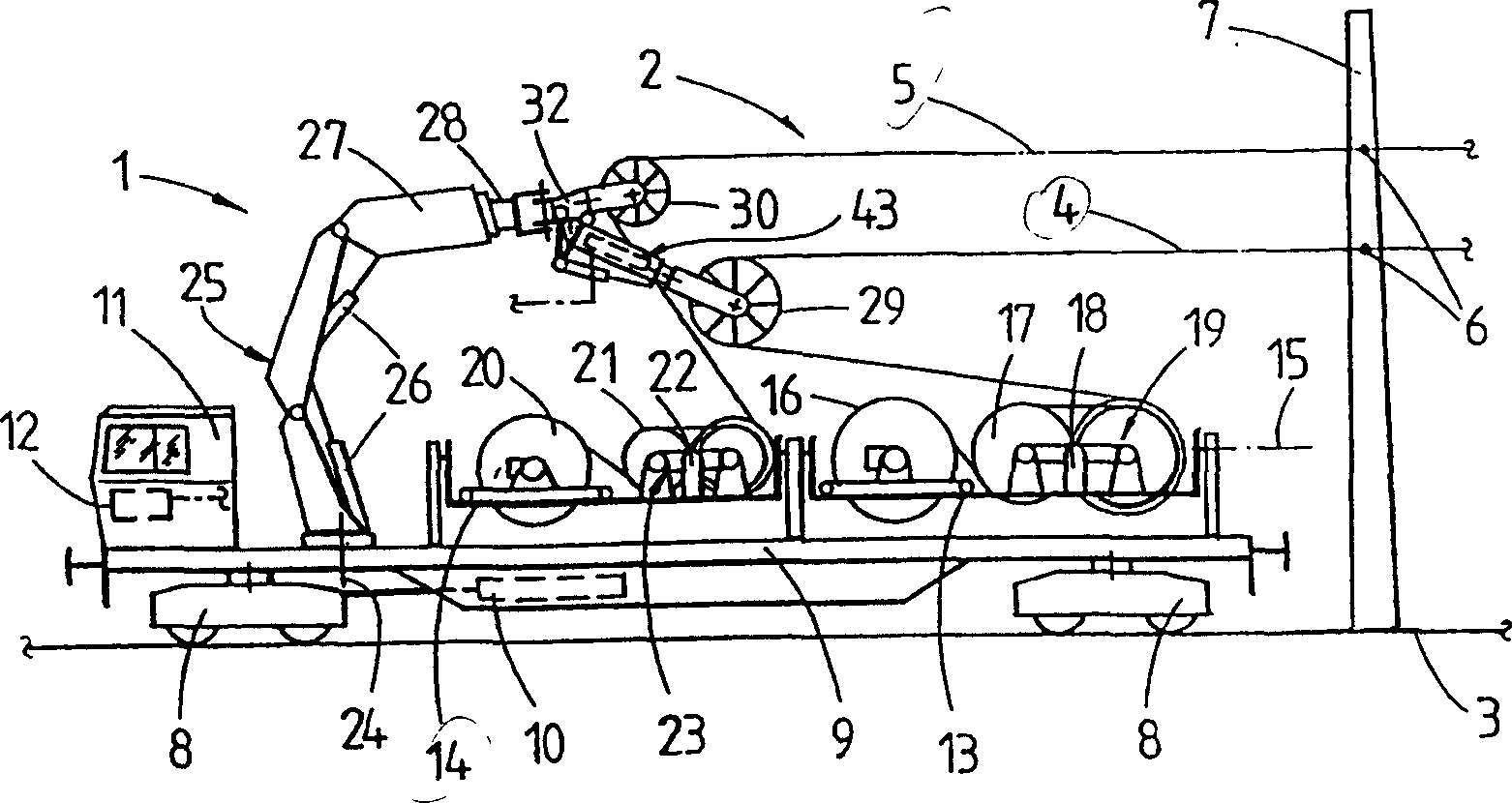
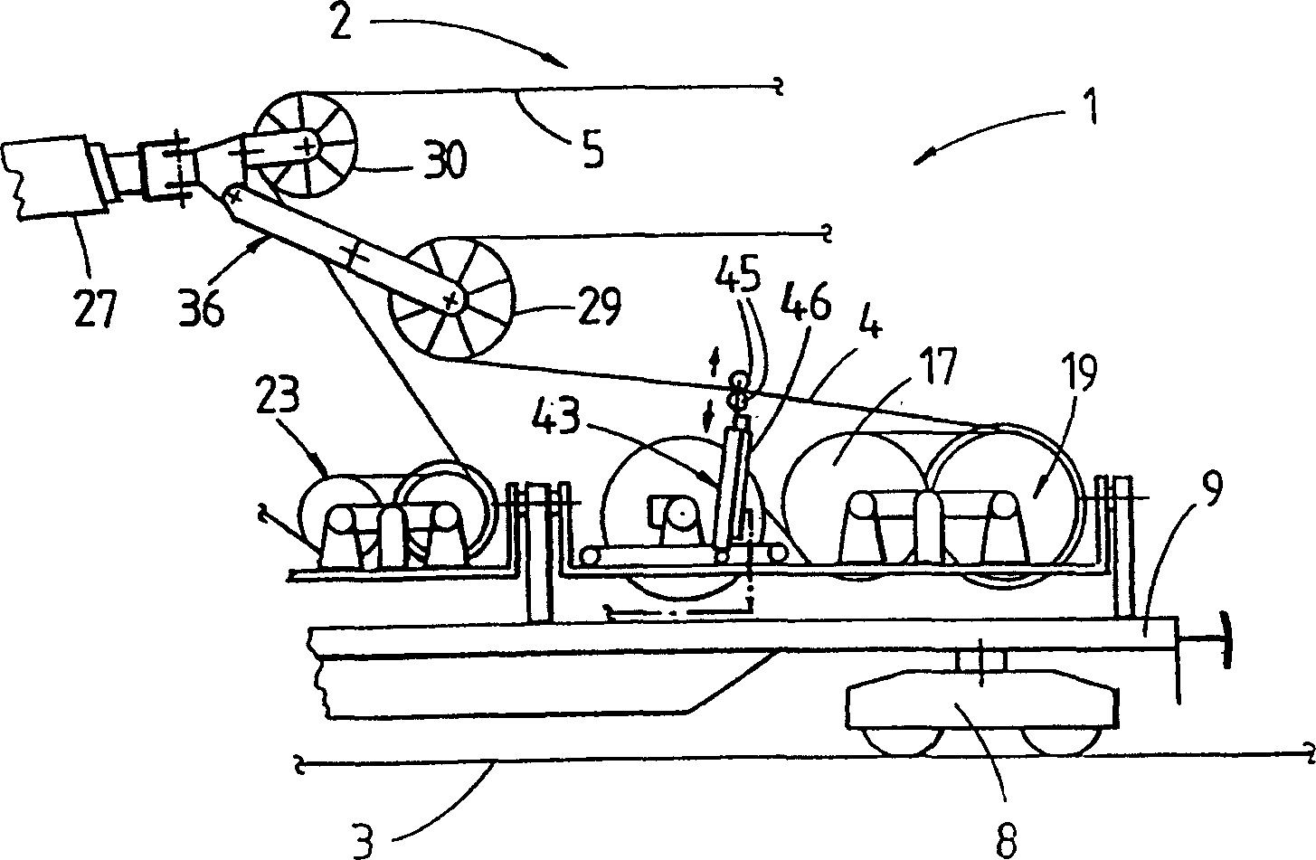
[0013] figure 1 Shown is a machine 1 for mounting rails 3 electrified catenary 2 . The catenary 2 is mainly composed of a contact wire 4 and a load-bearing cable 5 connected to the fixed point 6 of the catenary pole 7 beside the track. The machine 1 has a frame 9 supported on a rail 3 by means of a rail mechanism 8, and can travel along the rail 3 by means of a travel drive 10 and a control device 12 provided in the cab 11, ie, in the cab.

[0014] The frame 9 is provided with two supporting frames 13, 14 which are installed forward and backward along the longitudinal direction of the machine, and can swing back and forth around an axis 15 along the longitudinal direction of the machine. The carrier 13 is provided with a spool 16 on which the contact wires 4 are wound. There is also a rope winch 17 which can be actuated by means of a hydraulic drive 18 to form a tensile stressing device 19 . Similarly, a reel 20 of a load-bearing cable 5 and a rope winch 21 equipped with a ...


PUM


Abstract

A operation method for installing contact wire (4) of electrified contact system (2) or a catenary (5), wherein the contact wire (4) led on the setting height by the directive wheel (29) rolls down from the wire coil (16) on the machine (1) in the case of giving a given tension. In the transition period which the machine (1) is from statics to advancing operation, reducing the hold down mechanism pressure generated by that the hold down mechanism (43) reclining the contact wire (4) with tension, and increasing the hold down mechanism pressure in the transition period which the machine (1) is from advancing operation to statics.

Description

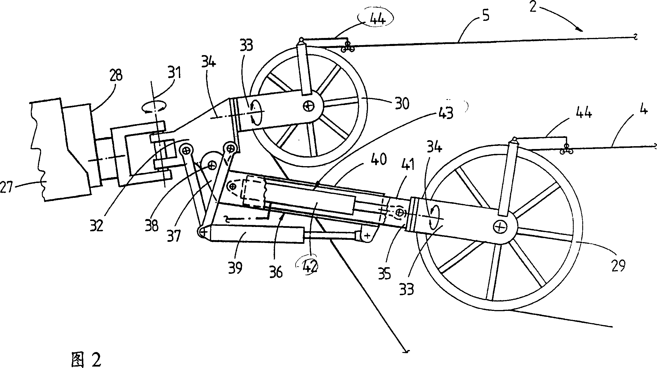
technical field [0001] The invention relates to an operation method for installing contact wires or load-bearing cables of an electrified catenary and a machine for installing the catenary. Background technique [0002] Patent EP 0416 136 describes such a method of operation. In this work method, the contact wires and the load-bearing cables of the electrified catenary are erected together or at the same time with the required given tension by the use of a rail machine. For this purpose, two carrying frames are provided on the machine frame, on which, respectively, the contact wires or the load-bearing cables are provided with reels and a tensile stress applying device in the form of a rope winch. The free end of a jib crane with adjustable height and lateral position mounted on the frame is equipped with a guide device consisting of two guide wheels that can be adjusted in height relative to each other. When the machine is continuously advancing for erection operations, t...

Claims


Application Information

Patent Timeline
IPC IPC(8): B60M1/28B61D15/00H02G11/02
CPCB60M1/28
Inventor 约瑟夫·陶依尔利奥波德·格鲁伯
Owner FRANZ PLASSER BAHNBAUMASCHINEN IND GMBH
Learn More