Miniaturized hydraulic electronic pump

A hydraulic, ultra-miniature technology, applied in liquid variable volume machinery, pumps, pumps with flexible working elements, etc., can solve the problems of poor ball valve positioning, poor working stability, easy pressure relief, etc., to improve the output power. , Good consistency, smooth in and out

Inactive Publication Date: 2004-08-04
胡军 +1
View PDF0 Cites 5 Cited by
  • Summary
  • Abstract
  • Description
  • Claims
  • Application Information

AI Technical Summary

Problems solved by technology

[0003] The purpose of the present invention is to develop a new type of ultra-miniature hydraulic electronic pump on the basis of the inventor's years of research and use of the ultra-miniature electronic pump and the original patent application, to overcome and solve the problem of the ultra-miniature electronic pump in the original technology under long-term work. Blockage, easy pressure relief, resulting in poor working stability, poor ball valve positioning and other problems. On the basis of ensuring the miniaturization of the volume, improve the flow rate and working efficiency of the pump, improve the quality and comprehensive performance of the product and the consistency of the product, and prolong the service life of the pump. The service life of the product is extended, the scope of use is expanded, and it is more suitable for large-scale industrial production

Method used


Image

  • Miniaturized hydraulic electronic pump
  • Miniaturized hydraulic electronic pump
  • Miniaturized hydraulic electronic pump

Examples


Embodiment Construction

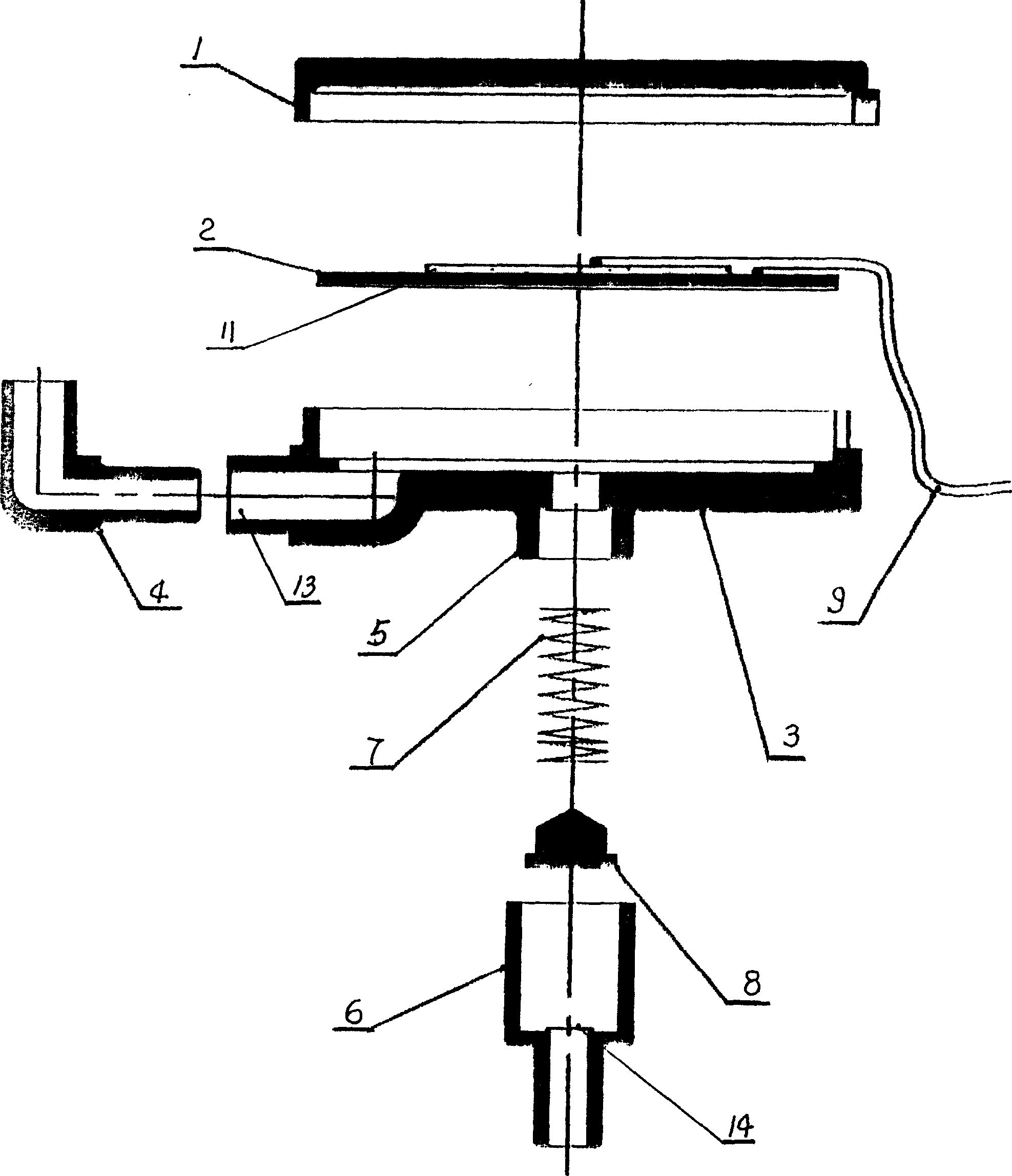
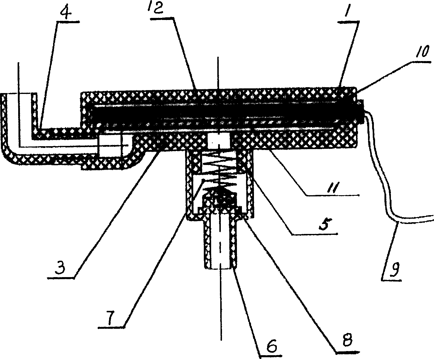
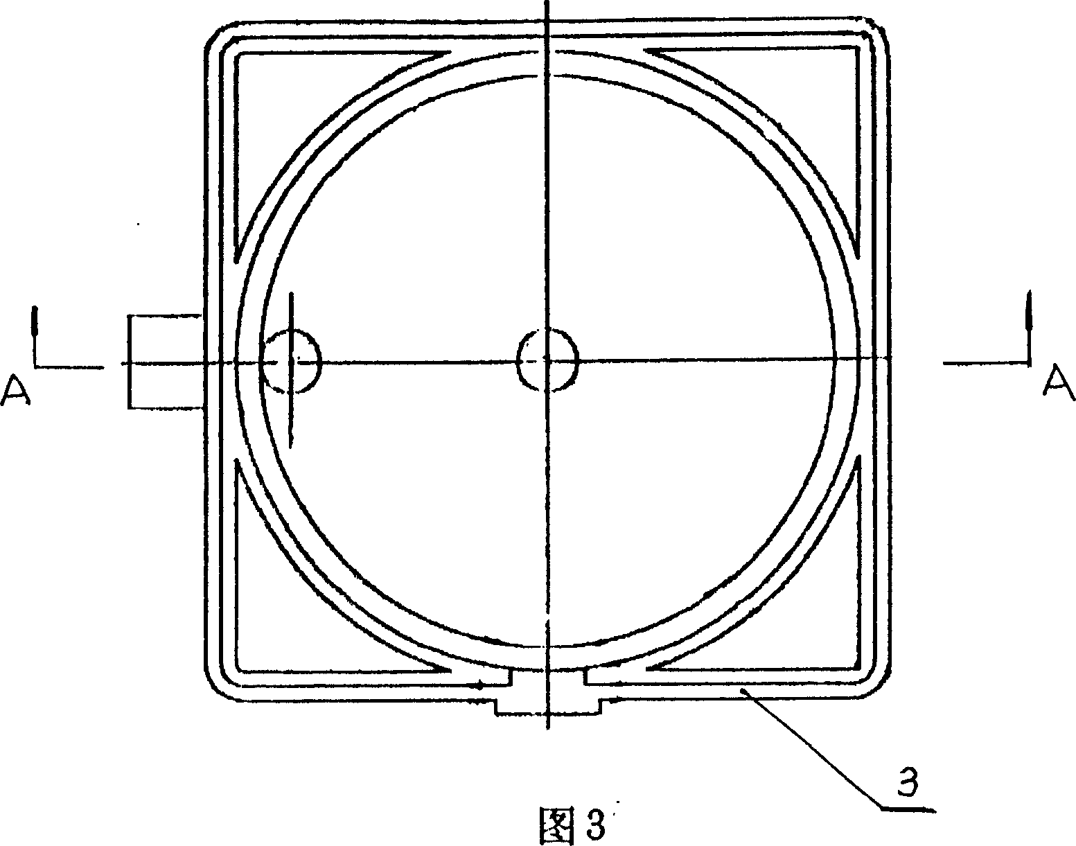
[0017] Further detailed description is made below according to the accompanying drawings: see figure 1 and figure 2 , the whole process and structure are: the concave cavity above the pump body 3 and the pump cover 1 form a pump cavity, there is a liquid inlet 5 in the middle of the pump body 3, and a liquid outlet 13 on the left. The piezoelectric ceramic transducer 2 is customized by the manufacturer or purchased in the market. Its parameters are high voltage 220V, 50Hz, 120V, 60Hz and low voltage below 42V, 50Hz or 60Hz, which are selected according to the user's requirements for the product. A piece of piezoelectric ceramic transducing sheet 2 is adopted (it can also be called an energy-enhancing sheet 12, but in order to distinguish the energy-enabling sheet 12 composed of a plurality of piezoelectric ceramic sheets 16 and a substrate 15, the piezoelectric ceramic is replaced in the present invention. Energy sheet 2 appellation unchanged) or energy sheet 12, its front w...


PUM


Abstract

The present invention relates to a hydraulic electron pump in new ultramicro-type to overcome the problems of low performance, easy blocking, easy decompressing and low efficiency of flow and operation existed in original technology, which consists of fixed piezoelectric ceramic inverting plate in pump cavity formed by pump body and pump cover, outer setting one way valve of liquid inlet in plug in individual piece, one way valve formed by valve gate assembled internally in valve body and spring. It has the advantages of large flow, not easy to block, convenient assembling, high finished product ratio, good uniformity of products and suitable for large scale production in industralization.

Description

(1) Technical field [0001] The invention relates to an ultra-miniature pump, specifically a novel ultra-miniature hydraulic electronic pump. (2) Background technology [0002] In the background technology, most of the hydraulic pumps generally sold on the market are mechanical, large in size, difficult to miniaturize, and difficult to install. In 2001, it began to be used in handicrafts, such as water spraying and flowing water handicrafts, Fengshui car humidifiers, etc.; the inventor applied for a patent "multi-purpose ultra-miniature electronic pump" in 2001. Although the pump overcomes and solves the problem that hydraulic pumps are not easy to reduce the volume , Difficult to install, small flow rate, low head, not easy to damage and fracture, etc. However, due to the miniaturization of the pump, the inner cavity of the pump is narrow, and the one-way valve installed in the cavity operates at fifty times per second during continuous and repeated work. The water or liqui...

Claims


Application Information

Patent Timeline
Patent Type & Authority Patents(China)
IPC IPC(8): F04B43/04
Inventor 胡军杨竹君
Owner 胡军
Why Eureka
Try Eureka