Pavement-vehicle convoy

A train and vehicle technology, applied in the field of paving trains, can solve problems such as difficult monitoring distances

Inactive Publication Date: 2004-07-14
JOSEPH VOEGELE AG
View PDF5 Cites 0 Cited by
  • Summary
  • Abstract
  • Description
  • Claims
  • Application Information

AI Technical Summary

Problems solved by technology

If there is at least one delivery vehicle in the paving train, it can be difficult to monitor especially the distance between the road finishing vehicles due to the presence of the delivery vehicle

Method used


Image

  • Pavement-vehicle convoy
  • Pavement-vehicle convoy
  • Pavement-vehicle convoy

Examples


Embodiment Construction

[0032] The various embodiments that will be described below are just a few. The detailed embodiments are only schematically shown and described so that the basic concept of the invention can be fully understood. Details in the field of control engineering and control engineering are also represented and explained in a simple manner, which in practice can be realized in clearly improved and more complex forms.

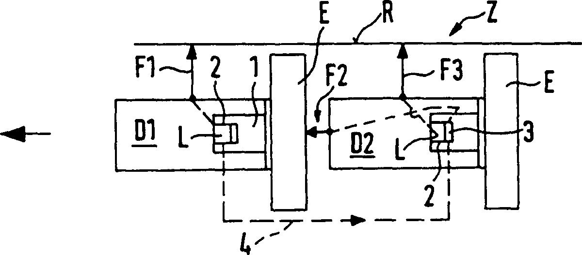
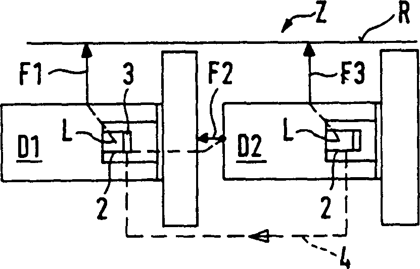
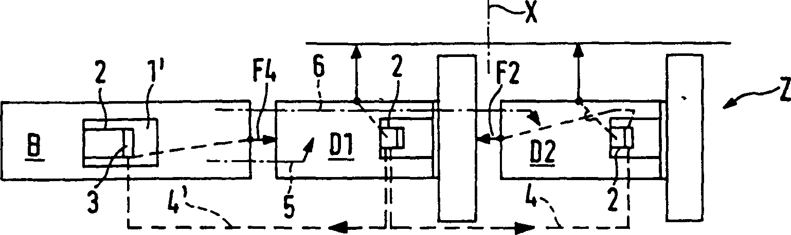
[0033] Paving train Z( figure 1 , 5 and 6) comprising at least two road finishing vehicles D1 and D2 traveling along a traveling reference line R at a predetermined distance Y from each other. Each road finishing vehicle D1, D2 comprises a driver's cab 1, and the driver's cab 1 has an operation control device 2, the operation control device 2 has, for example, an automatic direction control system L integrally, and drives the road paving leveler E , the leveler E has a road covering device, such as a compacting device 12 ( Figure 5). At least in the case of the op...


PUM


Abstract

A paving vehicle column (Z) which is used for generating coatings (15, 16) of asphalt or concrete pavement material (14) in traffic areas is provided, which includes at least two independently driven vehicles (D1, D, D3, B) that is suitable for being driven in the vehicle column, especially a plurality of pavement dressing vehicles or a feed wagon and at least one pavement dressing vehicle. At least on vehicle (D1, D, D3, B) in the paving vehicle column (Z) is used or suitable for being used as an instruction vehicle for telecontrolling other vehicles and operating other vehicles through remote control.

Description

technical field [0001] The invention relates to a paving train. Background technique [0002] To apply a layer of asphalt or concrete pavement material, for example in two layers, two or more vehicles are combined to form a paving train. The smallest paving train consists of two surfacing vehicles, or one surfacing vehicle and an associated delivery vehicle. In fact, a mechanical coupling (US-A-5100 277) is not possible in the case of self-propelled vehicles, since the respective driving movements necessarily do not coincide with each other for geometrical, mechanical and other reasons. So far, it has been the task for several drivers to keep the distance between the vehicles as constant as possible. In practical paving trains, the vehicles traveling in platoon are controlled by a corresponding number of very experienced drivers in their own control rooms with operating control devices. A so-called drive master plays the role of switching the drive of the chassis and of a...

Claims


Application Information

Patent Timeline
Patent Type & Authority Patents(China)
IPC IPC(8): E01C19/00E01C19/48G05D1/00G05D1/02
CPCG05D1/024G05D1/0291E01C19/48G05D2201/0202G05D1/0257G05D1/0255G05D1/0272E01C2301/04G05D1/0293
Inventor 罗兰·格林德耳阿尔弗雷德·乌尔里希
Owner JOSEPH VOEGELE AG
Why Eureka
Try Eureka