Micro-grid reactive compensation cabinet

A compensation cabinet and microgrid technology, applied in the field of electrical cabinets, can solve problems such as low efficiency, pollution damage to components, and increased safety hazards.

Pending Publication Date: 2022-08-09
李子健
View PDF0 Cites 0 Cited by
  • Summary
  • Abstract
  • Description
  • Claims
  • Application Information

AI Technical Summary

Problems solved by technology

[0003] The reactive power compensation cabinet will generate heat during operation. During use, it is necessary to discharge the heat in the compensation cabinet in time to prevent the internal heat of the compensation cabinet from being too high and causing damage to the components in it, thereby causing great safety hazards.
Existing heat dissipation methods for compensation cabinets mostly use vents, exhaust fans or cooling plates to dissipate heat, but this cooling method is inefficient. Particles such as dust in the air are brought into the compensation cabinet, causing pollution and damage to the components in the compensation cabinet, increasing the possibility of potential safety hazards, and reducing the service life of components inside the compensation cabinet

Method used


Image

  • Micro-grid reactive compensation cabinet
  • Micro-grid reactive compensation cabinet
  • Micro-grid reactive compensation cabinet

Examples


Embodiment Construction

[0030] In order to make it easy to understand the technical means, creation features, achieved goals and effects of the present invention, the present invention will be further described below with reference to the specific embodiments.

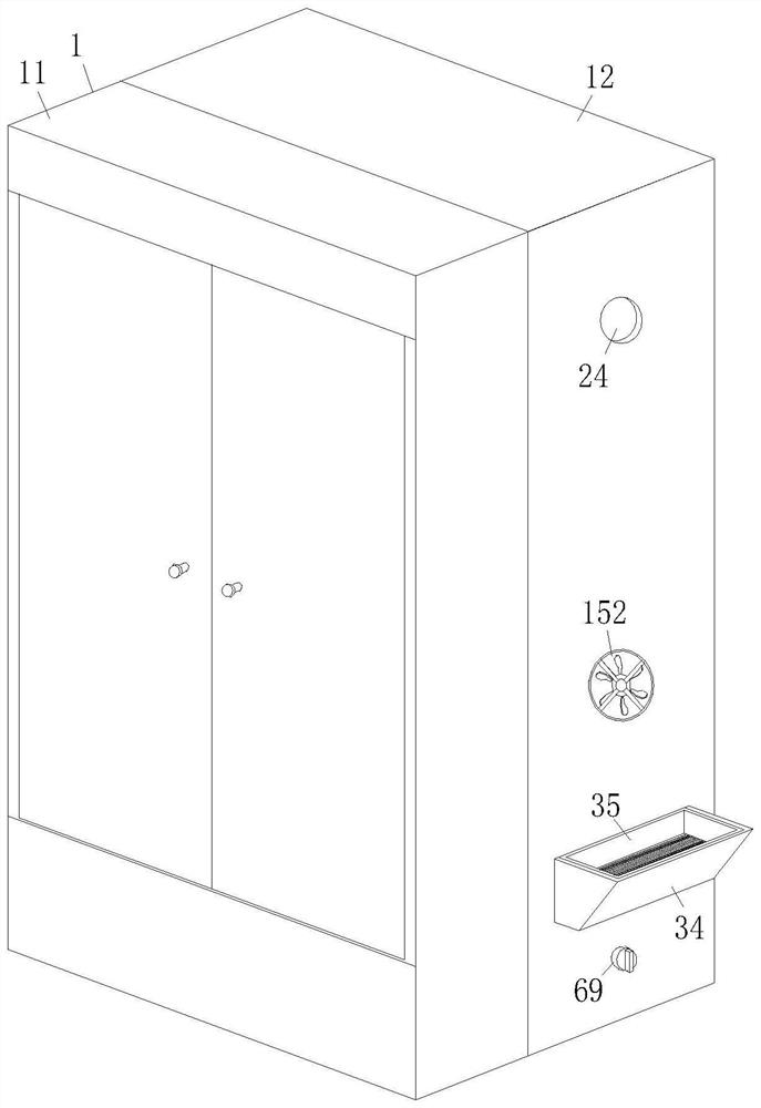
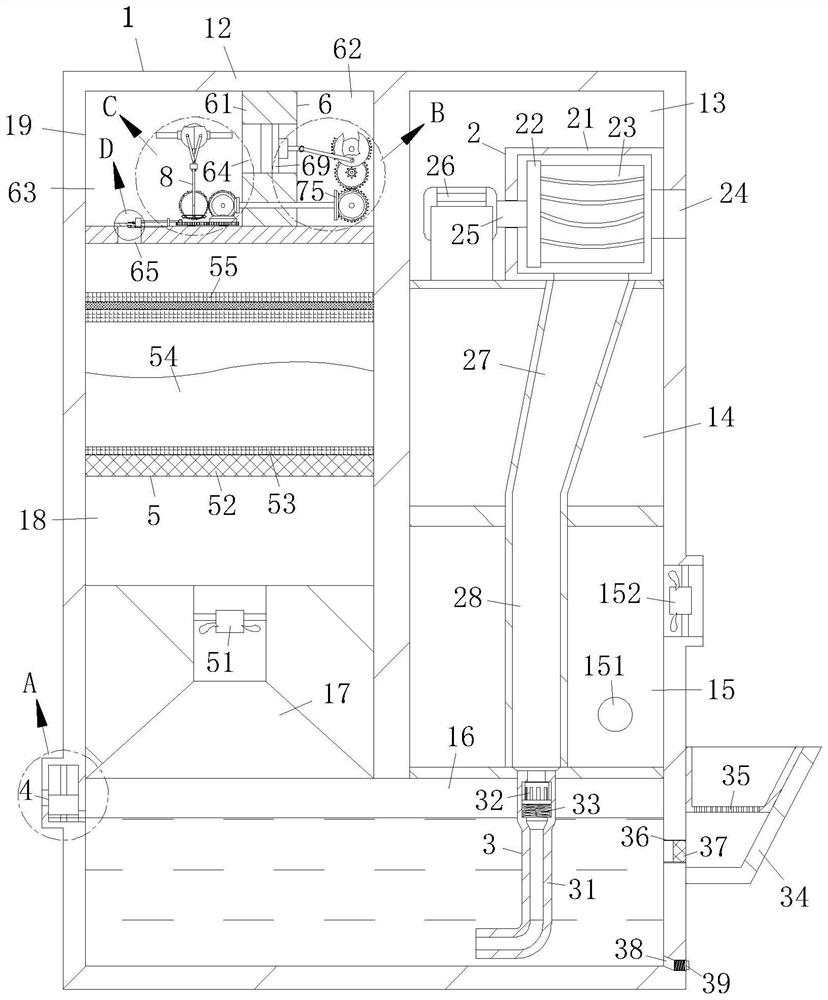
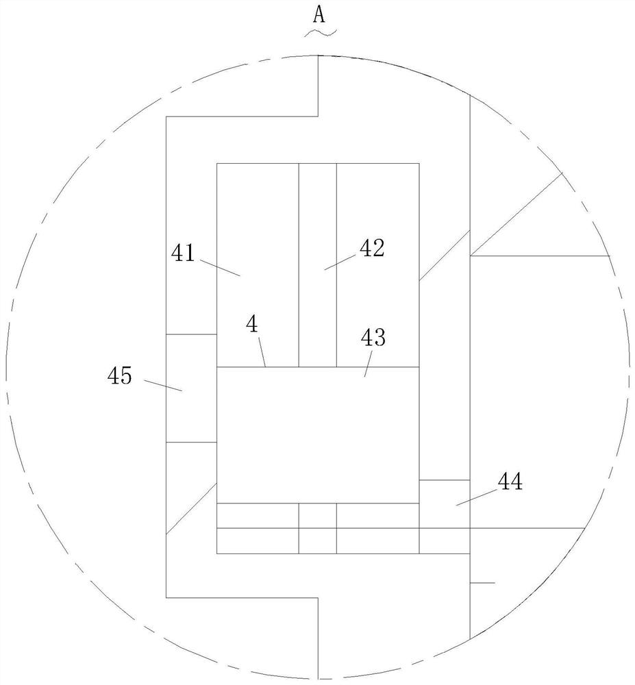
[0031] like Figure 1-Figure 6 As shown in the figure, a microgrid reactive power compensation cabinet according to the present invention includes a reactive power compensation cabinet 1, a blower mechanism 2, a cooling mechanism 3, a water control mechanism 4, a filter mechanism 5, a transfer mechanism 6, a linkage mechanism 7 and a closed The mechanism 8 is characterized in that: the reactive power compensation cabinet 1 includes a compensation cabinet body 11 and a cooling box 12, the blowing mechanism 2 is installed on the upper end side of the cooling box 12, the cooling mechanism 3 is arranged at the bottom of the cooling box 12, and the water control mechanism 4 is arranged On one side of the cooling mechanism 3, the filtering mechanis...


PUM


Abstract

The invention relates to the field of electrical cabinets, in particular to a micro-grid reactive power compensation cabinet which comprises a reactive power compensation cabinet body, an air blowing mechanism, a cooling mechanism, a water control mechanism, a filtering mechanism, a transfer mechanism, a linkage mechanism and a closing mechanism. When the height of the water level in the cooling cavity reaches the position of the water control valve groove, the water level enters the water control valve groove, the water control floating block ascends along the limiting thin rod under the influence of water buoyancy until the water outlet hole is opened, water in the cooling cavity can flow out of the water outlet hole, and monitoring and balancing of the water amount in the cooling cavity are achieved. External air is cooled through the cooling mechanism, meanwhile, dust particles in the air can be effectively filtered out, and it is guaranteed that purified air is clean; the cooling air is dried and filtered through the filtering mechanism, so that the dryness of the purified gas is ensured, and the gas entering the compensation cabinet main body is prevented from wetting and corroding parts in the compensation cabinet main body; the combination of the two can effectively prevent dust from polluting the internal structure of the compensation cabinet, and can effectively dissipate heat.

Description

technical field [0001] The invention relates to the field of electrical cabinets, in particular to a reactive power compensation cabinet of a microgrid. Background technique [0002] Microgrid refers to a small power generation and distribution system composed of distributed power sources, energy storage devices, energy conversion devices, loads, monitoring and protection devices. Reactive power compensation is a technology that improves the power factor of the power grid in the power supply system, reduces the loss of power supply transformers and transmission lines, improves power supply efficiency, and improves the power supply environment. [0003] The reactive power compensation cabinet will generate heat during operation. During the use process, it is necessary to discharge the heat in the compensation cabinet in time to prevent the internal heat of the compensation cabinet from being too high and causing damage to the components therein, thereby causing a great safety...

Claims


Application Information

Patent Timeline
Patent Type & Authority Applications(China)
IPC IPC(8): H02B1/30H02B1/56H02B1/28H02J3/18
CPCH02B1/30H02B1/565H02B1/28H02J3/18Y02E40/30
Inventor 李子健王平
Owner 李子健
Why Eureka
Try Eureka