System and method for testing manufacturing performance of permanent magnet motor

A test system and permanent magnet motor technology, applied in the direction of motor generator testing, manufacturing tools, measuring devices, etc., can solve the problems of reducing test time, affecting test efficiency, and failing to realize the fast connection between the output shaft and the torque sensor, etc., to achieve Improve the effect of the scope of application

Active Publication Date: 2022-08-09
苏州炽优装备科技有限公司
View PDF6 Cites 1 Cited by
  • Summary
  • Abstract
  • Description
  • Claims
  • Application Information

AI Technical Summary

Problems solved by technology

[0004] In the above prior art, the T-shaped sliding seat has a certain height from the bottom plate, so the motor needs to be transported to the T-shaped sliding seat. When the motor to be tested is large When the gravity is heavy, it is difficult to transport, while the traditional transport method is mainly lifted by manual or existing hoisting equipment, and its loading and unloading are slow, which affects the test efficiency; at the same time, the motor needs to be adjusted after it is transported to the T-shaped slide. position to ensure that the motor can be connected to the torque sensor, it will take a lot of time to adjust the position of the motor, which further affects the efficiency of the motor test; at the same time, the output shaft of the motor is connected to the torsion sensor through a coupling, so every time the motor is tested The output shaft needs to be connected to the coupling, and the output shaft and the torque sensor are not quickly connected to reduce the test time; and when the diameter of the output shaft is different for motors of different specifications, different couplings need to be replaced The device can be connected, which further affects the test efficiency of the motor

Method used


Image

  • System and method for testing manufacturing performance of permanent magnet motor
  • System and method for testing manufacturing performance of permanent magnet motor
  • System and method for testing manufacturing performance of permanent magnet motor

Examples


Embodiment 1

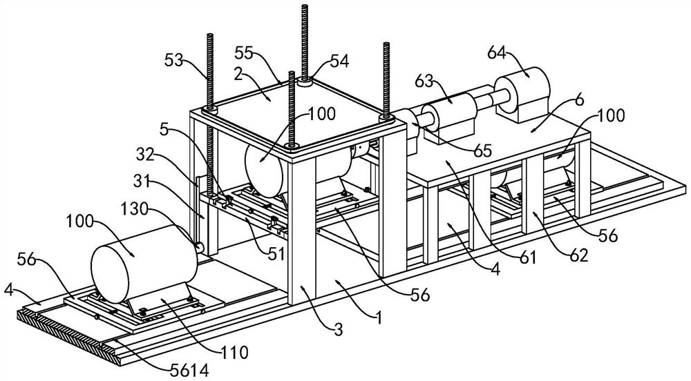
[0040] see figure 1 , this embodiment discloses a permanent magnet motor manufacturing performance testing system, including a base plate 1 installed on an existing platform, a top plate 2 placed horizontally above the base plate 1, and the top plate 2 is supported by four vertical plates. 3 is fixed on the base plate 1, the base plate 1 and the left and right sides of the top plate 2 are provided with a sliding platform 4, the top plate 2 is provided with a lifting device 5, and the right side of the top plate 2 is provided with a motor 64 for detecting the output Shaft torsion detection device 6 .

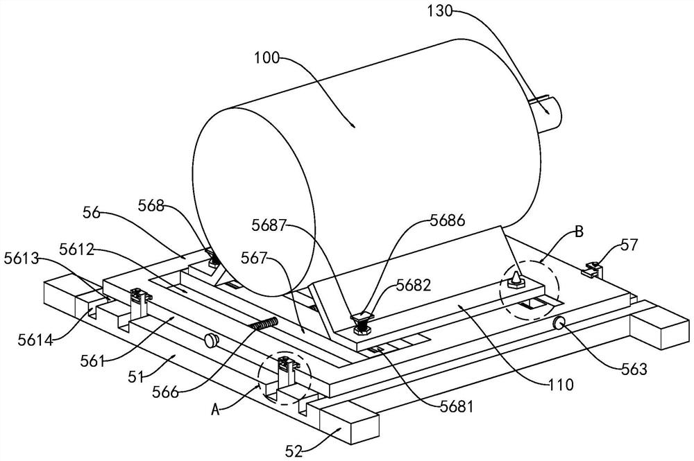
[0041] see figure 1 and figure 2 , the lifting device 5 includes a lifting platform 51 slidably arranged under the top plate 2, the front and rear ends of the lifting platform 51 are provided with two lifting parts 52 symmetrically distributed on the left and right, and the lifting parts 52 are rotatably connected with lifting wires Rod 53, the upper end of the lift screw 53 ...

Embodiment 2

[0054] see figure 1 and Figure 7 On the basis of the first embodiment, in order to ensure that the motor output shafts 130 of different specifications can be docked with the detection device 6, and at the same time to ensure that the motor output shaft 130 is quickly docked with the detection device 6, the detection device 6 includes a The installation platform 61 located above and on the right side of the top plate 2, the installation platform 61 is fixed on the base plate 1 through a plurality of supporting legs 62, and a torque sensor 63 is installed on the installation platform 61 through the installation seat, the right end of the torque sensor 63 is The input shaft of the torque sensor 63 is connected with the output shaft of the detection motor 64 through the coupling, the detection motor 64 is installed on the installation platform 61 through the motor base, and the output shaft of the left end of the torque sensor 63 is connected with the docking mechanism 65 install...


PUM


Abstract

The invention relates to the technical field of permanent magnet motor testing, in particular to a permanent magnet motor manufacturing performance testing system and method.The permanent magnet motor manufacturing performance testing system comprises a base plate installed on an existing platform, a horizontally-arranged top plate is arranged above the base plate, and the top plate is fixed to the base plate through four supporting vertical plates; sliding platforms are arranged on the base plate and located on the left side and the right side of the top plate, a lifting device is arranged on the top plate, and a detection device used for detecting torsion of a motor output shaft is arranged on the right side of the top plate. Through cooperation of the sliding platform and the lifting platform, the function of assembly line type performance testing of the permanent magnet motor can be achieved. The clamping unit is mainly used for clamping and fixing the permanent magnet motor and moving and carrying the permanent magnet motor on the sliding platform and the lifting platform. The motor output shaft and the butt joint can be quickly inserted through the butt joint mechanism, meanwhile, butt joint of motor output shafts of different specifications can be achieved through second spline shafts of different specifications, and the application range of the motor output shaft butt joint device is widened.

Description

technical field [0001] The invention relates to the technical field of permanent magnet motor testing, in particular to a permanent magnet motor manufacturing performance testing system and method. Background technique [0002] The permanent magnet motor uses permanent magnets to provide excitation, which makes the motor structure simpler, reduces the processing and assembly costs, and saves the slip rings and brushes that are prone to problems, which improves the reliability of motor operation; and because no excitation current is required , There is no excitation loss, which improves the efficiency and power density of the motor. The motor transmits torque through the output shaft. Therefore, the motor needs to test the output shaft torque of the motor during production to ensure that the output shaft torque meets the specified requirements. [0003] In the prior art, such as a motor output shaft torque testing device provided by publication number CN211477471U, it include...

Claims


Application Information

Patent Timeline
Patent Type & Authority Applications(China)
IPC IPC(8): G01L3/00G01R31/34B25B11/00
CPCG01L3/00G01R31/34B25B11/00
Inventor 瞿叶胜肖卫刚
Owner 苏州炽优装备科技有限公司
Why Eureka
Try Eureka