
Novel welding ball valve

A welded ball, a new type of technology, applied in the field of new welded ball valves, can solve the problems of poor sealing effect, poor sealing performance, increased pump load, etc., and achieve the effects of eliminating cavitation, good sealing performance, and high thermal conductivity

Pending Publication Date: 2022-08-09
河北玖际管道制造有限公司
View PDF0 Cites 0 Cited by
  • Summary
  • Abstract
  • Description
  • Claims
  • Application Information

AI Technical Summary

Problems solved by technology

[0004] 1. The D15-DN200 on the market are all floating balls, and those above 200 can’t be floating balls, they are all fixed balls. The valve blocks of floating ball valves on the market usually have high hardness, poor cushioning, and almost no cushioning. In addition, the valve block It is difficult to fit tightly with the outlet, resulting in poor sealing. When the liquid pressure is low, leakage may still occur, and the tight seal cannot be completed, resulting in poor sealing effect
[0005] 2. Due to the rough design inside the traditional ball valve, when the water flow passes through, at least eight parts will generate turbulent flow, which seriously affects the flow rate and increases the load of the pump. The traditional ball valve does not have a compression cock setting, which cannot ensure the complete tightness of the sealing material , requires frequent maintenance, and the ball valve seals on the traditional market are all sealed with rubber O-rings, which are easy to age and need to be replaced regularly

Method used


Image

  • Novel welding ball valve
  • Novel welding ball valve
  • Novel welding ball valve

Examples


Embodiment Construction

[0026] The technical solutions in the embodiments of the present invention will be clearly and completely described below with reference to the accompanying drawings in the embodiments of the present invention. Obviously, the described embodiments are only a part of the embodiments of the present invention, but not all of the embodiments. Based on the embodiments of the present invention, all other embodiments obtained by those of ordinary skill in the art without creative efforts shall fall within the protection scope of the present invention.

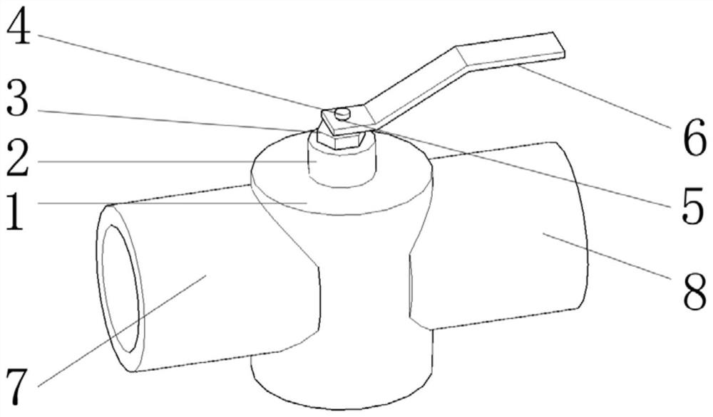
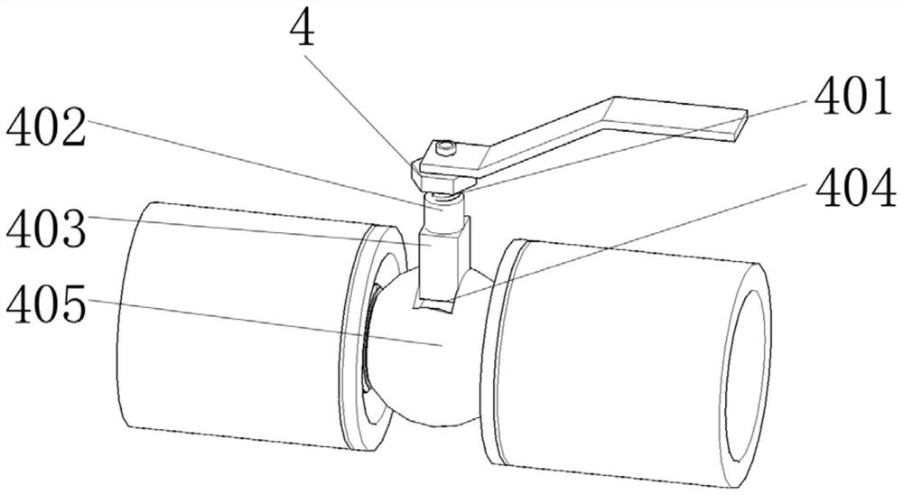
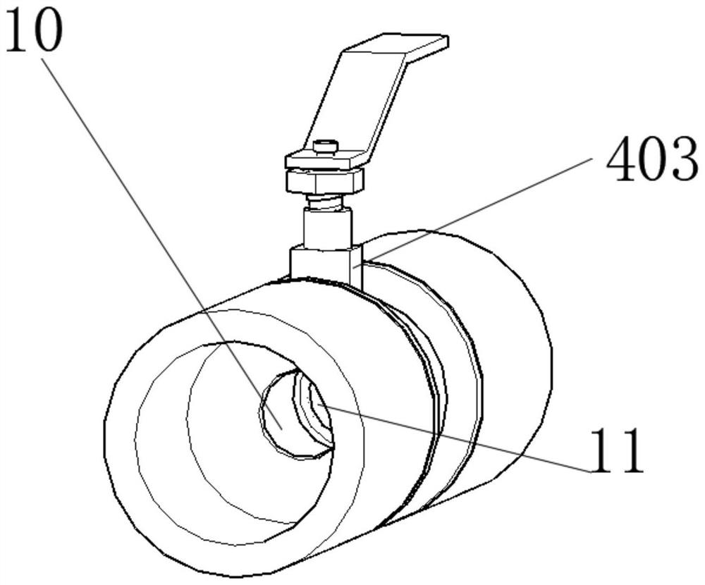
[0027] see Figure 1-5 , the embodiment of the present invention provides a technical solution: a new type of welded ball valve, including a valve body 1, the valve body 1 includes a fixed block 2, an adjustment nut 3, a limit block 4 and a valve ball body 405. The valve body 1. The top is welded with the bottom of the fixed block 2. The top of the fixed block 2 is provided with an adjusting nut 3, and the adjusting nut 3 is slidably ...


PUM


Abstract

The novel welding ball valve comprises a valve main body, the valve main body comprises a fixing block, an adjusting nut, a limiting block and a valve ball main body, the top of the valve main body is welded to the bottom of the fixing block, the adjusting nut is arranged at the top of the fixing block, and the adjusting nut is slidably connected with a connecting shaft; the top end of the connecting shaft is sleeved with a handle, the top end of the connecting shaft is welded to the bottom of the limiting block, a first connecting pipe is welded to one side of the valve body, a second connecting pipe is welded to the other side of the valve body, and the first connecting pipe and the second connecting pipe communicate with the interior of the valve body; according to the novel welding ball valve, when the novel welding ball valve is used, under the pressure of liquid, a valve ball can move in the valve ball, sealing rings are attached more tightly, and meanwhile the novel welding ball valve has certain buffering performance, can bear larger hydraulic pressure and is better in sealing performance.

Description

technical field [0001] The invention relates to the technical field of ball valves, in particular to a novel welded ball valve. Background technique [0002] Ball valve is an on-off valve, which is widely used in the chemical industry and long-distance pipelines to regulate and control fluids. [0003] At present, the existing ball valves have the following shortcomings: [0004] 1. D15-DN200 on the market are all floating balls, and those above 200 cannot be floating balls, they are all fixed balls. The valve blocks of floating ball valves on the market usually have high hardness, poor cushioning, and almost no cushioning. In addition, the valve block It is difficult to fit closely with the outlet, resulting in poor sealing performance. When the liquid pressure is low, leakage may still occur, and tight sealing cannot be completed, resulting in poor sealing effect. [0005] 2. Due to the rough design inside the traditional ball valve, turbulent flow will occur in at least...

Claims


Application Information

Patent Timeline
Patent Type & Authority Applications(China)
IPC IPC(8): F16K5/20F16K39/06F16K27/06F16K27/10F16K5/06F16K47/02F16K31/60
CPCF16K5/205F16K5/20F16K39/06F16K27/067F16K27/107F16K5/0605F16K5/0684F16K47/023F16K31/60
Inventor 赵云浩
Owner 河北玖际管道制造有限公司
Learn More