
Swing stopping detection method and device of MEMS scanning mirror and laser radar

A technology of laser radar and scanning mirror, which is applied in the direction of measuring device, electromagnetic wave re-radiation, radio wave measurement system, etc., can solve problems such as MEMS scanning mirror damage, threat to human eye safety, MEMS scanning mirror driver damage, etc., to improve accuracy The effect of increasing the efficiency, improving the reliability of ranging, and avoiding damage

Active Publication Date: 2022-08-05
ZVISION TECH CO LTD
View PDF11 Cites 0 Cited by
  • Summary
  • Abstract
  • Description
  • Claims
  • Application Information

AI Technical Summary

Problems solved by technology

[0003] At present, during the working process of the laser radar, the MEMS scanning mirror will be damaged or the driver of the MEMS scanning mirror will be damaged, causing the MEMS scanning mirror to stop scanning and swinging (also can be described as MEMS scanning mirror shutdown), which will affect the ranging performance of the laser radar.
In addition, after the MEMS scanning mirror stops swinging, the outgoing light always shines at the same angle, which may threaten the safety of human eyes

Method used


Image

  • Swing stopping detection method and device of MEMS scanning mirror and laser radar
  • Swing stopping detection method and device of MEMS scanning mirror and laser radar
  • Swing stopping detection method and device of MEMS scanning mirror and laser radar

Examples


Embodiment Construction

[0033] In the following description, for the purpose of illustration rather than limitation, specific details such as specific system structures and technologies are set forth in order to provide a thorough understanding of the embodiments of the present invention. However, it will be apparent to those skilled in the art that the present invention may be practiced in other embodiments without these specific details. In other instances, detailed descriptions of well-known systems, devices, circuits, and methods are omitted so as not to obscure the description of the present invention with unnecessary detail.

[0034] In order to illustrate the technical solutions described in the present application, the following specific embodiments are used for description.

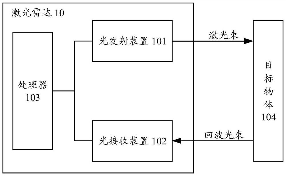
[0035] Lidar is a target detection technology. Lidar emits a laser beam through a laser, and the laser beam encounters the target object and diffuse reflection occurs, and the reflected beam is received by the detector...


PUM


Abstract

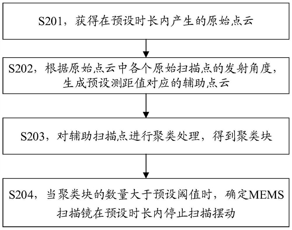
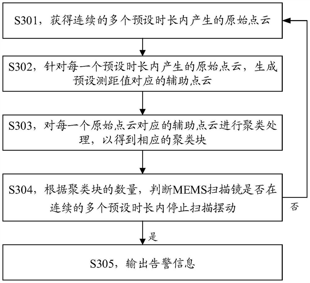
The invention discloses a stop swing detection method and device of an MEMS scanning mirror and a laser radar. The method comprises the following steps: acquiring an original point cloud generated by a laser radar within a preset time length; auxiliary point clouds corresponding to a preset distance measurement value are generated, auxiliary scanning points in the auxiliary point clouds are in one-to-one correspondence with original scanning points in the original point clouds, and the emission angles of the corresponding auxiliary scanning points and original scanning points are the same; performing clustering processing on the auxiliary scanning points to obtain clustering blocks; when the number of the clustering blocks is larger than a preset threshold value, it is determined that the MEMS scanning mirror stops scanning swing within the preset duration. The invention relates to a method. The original point cloud is subjected to clustering processing from the dimension of the emission angle, and then whether the MEMS scanning mirror stops scanning and swinging within the preset duration is judged, so that detection of stopping and swinging of the MEMS scanning mirror is realized.

Description

technical field [0001] The present application relates to the technical field of lidar, and in particular, to a method, device and lidar for stall detection of a micro electromechanical systems (MEMS) scanning mirror. Background technique [0002] Lidar is a target detection technology. The laser is used as the signal light source, and the reflected signal of the target object is collected by emitting laser light to the target object, so as to obtain the orientation, speed and other information of the target object. Lidar has the advantages of high measurement accuracy and strong anti-interference ability, and is widely used in remote sensing, measurement, intelligent driving, robotics and other fields. [0003] At present, during the operation of the lidar, the MEMS scanning mirror is damaged or the MEMS scanning mirror driver is damaged, which causes the MEMS scanning mirror to stop scanning and swinging (which can also be described as MEMS scanning mirror stoppage), ther...

Claims


Application Information

Patent Timeline
Patent Type & Authority Applications(China)
IPC IPC(8): G01S7/497G01S17/08
CPCG01S7/497G01S17/08
Inventor 陈森柯夏冰冰石拓
Owner ZVISION TECH CO LTD
Learn More