Hydraulic forced sealing flat gate valve
A technology of forced sealing, flat gate valve, applied in valve device, valve detail, sliding valve, etc., can solve the problem of reduced sealing performance, and achieve the effect of reducing leakage, reducing sealing cost and improving sealing effect
- Summary
- Abstract
- Description
- Claims
- Application Information
AI Technical Summary
Problems solved by technology
Method used
Image
Examples
Embodiment 1
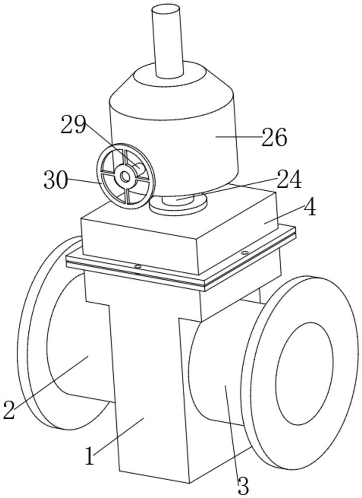
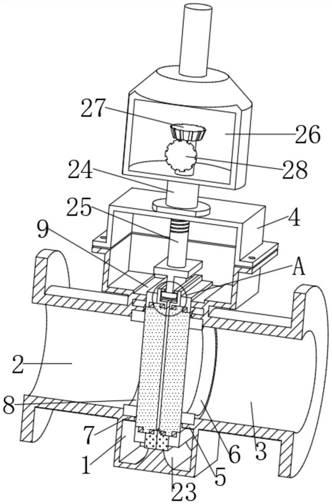
[0028] refer to Figure 1-5 , a hydraulic forced sealing flat gate valve, comprising a valve body 1, the valve body 1 is provided with two gates 10 symmetrically distributed on both sides, the top and the bottom of the gate 10 are provided with a limiting portion 11, the limiting portion 11 It has an integral structure with the gate 10 , first grooves 12 are opened on both sides of the limiting portion 11 , and the opposite side of the two limiting portions 11 is fixedly connected with a return spring 13 , and the other side of the return spring 13 is fixedly connected with a The first valve seat 14, the opposite sides of the two first valve seats 14 are fixedly connected with the second valve seat 15, and the opposite sides of the two second valve seats 15 located above are provided with second grooves 16. A piston 18 and a pressure block 19 are arranged between the second grooves 16 . The pressure block 19 is arranged above the piston 18 . A boss 23 is provided inside the bo...
Embodiment 2
[0039] refer to Figure 1-5 , a hydraulic forced sealing flat gate valve, comprising a valve body 1, the valve body 1 is provided with two gates 10 symmetrically distributed on both sides, the top and the bottom of the gate 10 are provided with a limiting portion 11, the limiting portion 11 It has an integral structure with the gate 10 , first grooves 12 are opened on both sides of the limiting portion 11 , and the opposite side of the two limiting portions 11 is fixedly connected with a return spring 13 , and the other side of the return spring 13 is fixedly connected with a The first valve seat 14, the opposite sides of the two first valve seats 14 are fixedly connected with the second valve seat 15, and the opposite sides of the two second valve seats 15 located above are provided with second grooves 16. A piston 18 and a pressure block 19 are arranged between the second grooves 16 . The pressure block 19 is arranged above the piston 18 . A boss 23 is provided inside the bo...
PUM
 Abstract
Description
Claims
Application Information
 - R&D
- Intellectual Property
- Life Sciences
- Materials
- Tech Scout
- Unparalleled Data Quality
- Higher Quality Content
- 60% Fewer Hallucinations
Browse by: Latest US Patents, China's latest patents, Technical Efficacy Thesaurus, Application Domain, Technology Topic, Popular Technical Reports.
© 2025 PatSnap. All rights reserved.Legal|Privacy policy|Modern Slavery Act Transparency Statement|Sitemap|About US| Contact US: help@patsnap.com


