
Multipurpose liquid cargo tank pipeline system and control method thereof

A pipeline system and cargo tank technology, applied in the field of clean fuel supply for ships, can solve the problems of not being able to make full use of different fuels from different gas sources, fixing the way of connecting pipelines, etc., so as to improve operation safety, flexible design and convenient operation. Effect

Active Publication Date: 2022-08-05
CHINA MERCHANTS HEAVY IND SHENZHEN +1
View PDF6 Cites 0 Cited by
  • Summary
  • Abstract
  • Description
  • Claims
  • Application Information

AI Technical Summary

Problems solved by technology

[0003] In the prior art, limited by the molecular weight of different fuels and inert gases, generally only a single fuel and inert gas can be used, and the way of connecting pipelines is also very fixed, which makes it impossible to make full use of different gas sources or different fuels, and the application is limited

Method used


Image

  • Multipurpose liquid cargo tank pipeline system and control method thereof
  • Multipurpose liquid cargo tank pipeline system and control method thereof
  • Multipurpose liquid cargo tank pipeline system and control method thereof

Examples


Embodiment 1

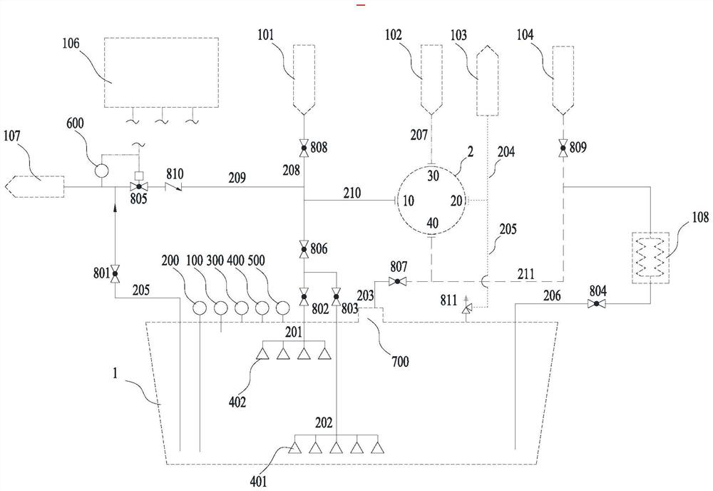
[0041] A multi-purpose cargo tank piping system for volume ≤ 1500m 3 and cargo tanks (1) with working pressure ≥ 4 barg, such as figure 1 As shown, it includes a cargo tank 1 at the lower end, a blow-off gas source 102 at the upper end, a vent mast 103, and an annular four-way connecting pipe 2; the multi-purpose cargo tank 1 pipeline system also includes connecting pipelines and equipment A valve on the connecting pipeline, and a bilge nozzle assembly 401 located at one end of the connecting pipeline and located at the bottom of the cargo tank 1, and a top nozzle assembly 402 located at the top of the cargo tank 1;

[0042] The molecular weight of the inert gas is smaller than the molecular weight of air, that is, when the inert gas is nitrogen, the inert gas starts from the purge gas source 102 and enters the cargo tank 1 from the top of the cargo tank 1; the air discharged from the bilge Starting from the nozzle assembly 401, it is discharged through the connecting pipelin...

Embodiment 2

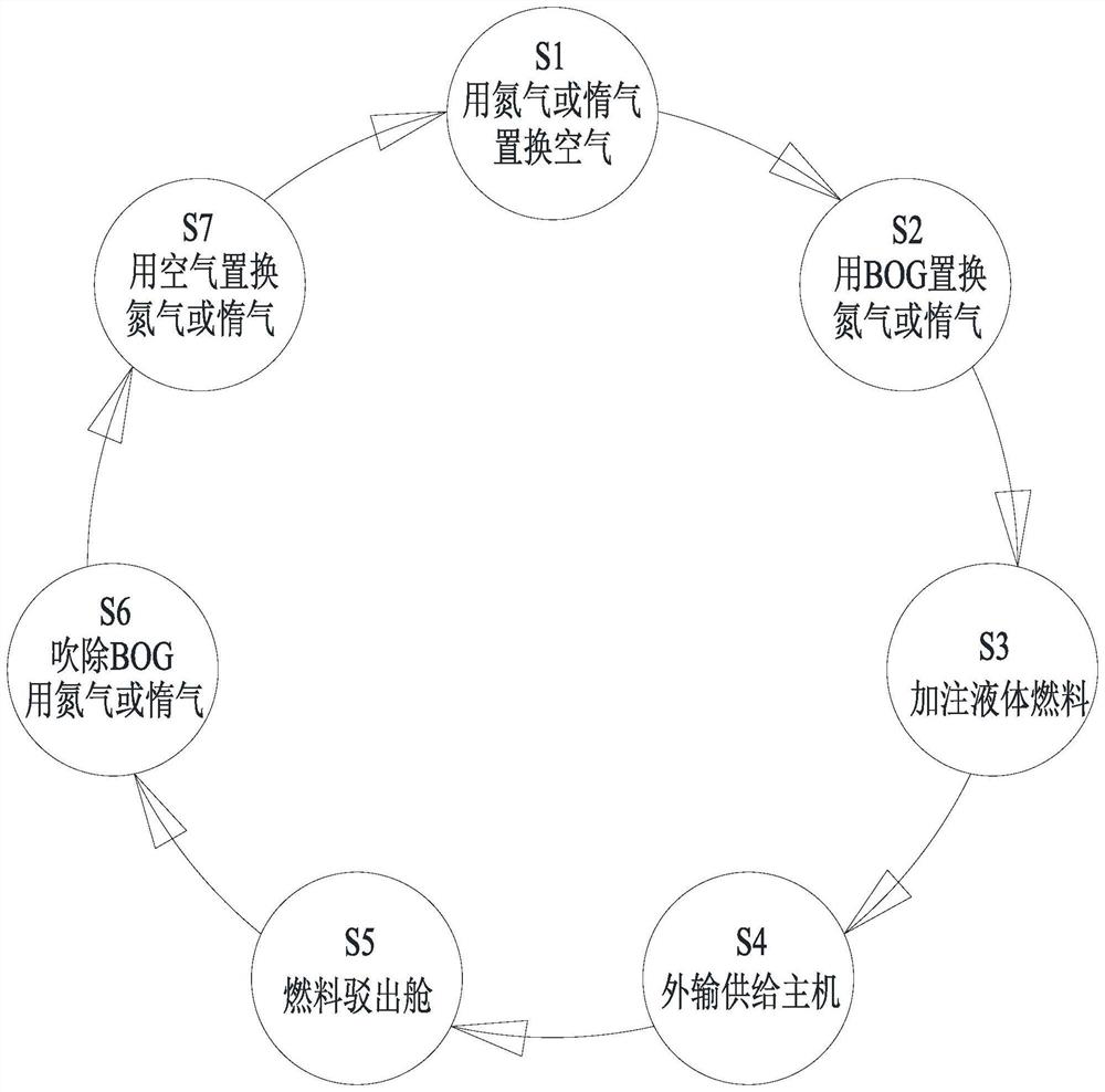
[0055] The present invention is aimed at the cargo tank 1 with a volume of ≤1500m3 and a working pressure of ≥4barg. Figure 1 to Figure 3 As shown, its control method is:

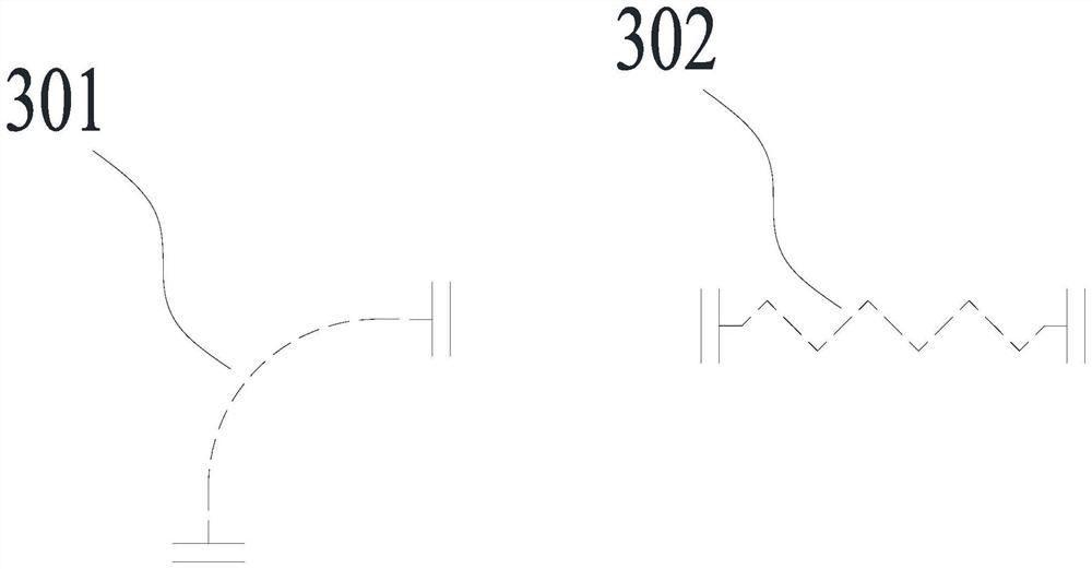
[0056] S1: Before filling tank 1, replace the air in the tank with nitrogen or inert gas. Such as nitrogen, install the detachable straight pipe 302 to connect the third nozzle 30 and the fourth nozzle 40. The nitrogen source starts from the seventh pipeline 207 and enters the cargo tank 1 through the seventh control valve 807 and the third pipeline 203. For purging, the displaced air is connected through the nozzle of the bilge nozzle assembly 401, the second pipeline 202, the sixth control valve 806, the tenth pipeline 210, the first nozzle 10 and the second nozzle 20 (can be installed by Remove the straight pipe 302), and then discharge it to the vent mast 103 through the fourth pipeline 204, and the completion signal is: the low-level detector 200 detects that the oxygen concentration in the bilge is ...


PUM


Abstract

The invention discloses a multipurpose liquid cargo tank pipeline system and a control method thereof. The multipurpose liquid cargo tank pipeline system comprises a liquid cargo tank arranged at the lower end, a blow-off gas source arranged at the upper end, a ventilation mast and an annular four-way connecting pipe. The system further comprises a connecting pipeline, a valve arranged on the connecting pipeline, a tank bottom pipe nozzle assembly arranged at one end of the connecting pipeline and located at the bottom of the liquid cargo tank, and a tank top pipe nozzle assembly located at the top of the liquid cargo tank. If the molecular weight of the inert gas is smaller than that of the air, the inert gas starts from a blow-off gas source, reaches the top of the liquid cargo tank and enters the liquid cargo tank; exhausted air starts from the bilge nozzle assembly, passes through the connecting pipeline and the annular four-way connecting pipe and is exhausted to the ventilation mast; if the molecular weight of the inert gas is larger than that of the air, the inert gas starts from a blow-off gas source, reaches the bilge nozzle assembly and enters the liquid cargo tank; and discharged air is discharged from the top of the liquid cargo tank to the connecting pipeline and the annular four-way connecting pipe to the ventilation mast.

Description

technical field [0001] The invention relates to the technical field of clean fuel supply for ships, in particular to a multi-purpose cargo tank piping system and a control method thereof. Background technique [0002] With the further emission reduction requirements of nitrogen oxides, sulfur oxides and carbon emissions in relevant regulations of the International Maritime Organization, the main engines of large ships have begun to be converted from traditional diesel and heavy oil to use various clean energy as fuel. The main energy sources are LNG, LPG, LNH3, etc. They have a common feature that they are gaseous at normal temperature and pressure. In order to facilitate the storage of more fuels in the limited space on board, they need to be pressurized and cryogenically processed in the gaseous state to make them phase-to-liquid and stored in dedicated cargo tanks on ships. These liquid fuels will evaporate in a phase change as the pressure and temperature change in the ...

Claims


Application Information

Patent Timeline
Patent Type & Authority Applications(China)
IPC IPC(8): B63B17/00B63J2/14
CPCB63B17/0027B63J2/14Y02T10/30
Inventor 孙瑞司徒颖峰赵立玉张家茂杨威黄朝俊胡成龙何大涛杜恒王登
Owner CHINA MERCHANTS HEAVY IND SHENZHEN
Learn More