
Variable-speed pumped storage generator motor with electric axial flow-centrifugal radial axial pressurization end ventilation system

A generator motor, radial ventilation technology, applied in the direction of hydropower, electric components, magnetic circuit rotating parts, etc., can solve the problems of unreasonable ventilation and cooling design, high temperature of stator end windings, to improve flow and pressure, improve Surface heat dissipation coefficient, the effect of accelerating the flow rate

Pending Publication Date: 2022-08-02
HARBIN UNIV OF SCI & TECH
View PDF0 Cites 0 Cited by
  • Summary
  • Abstract
  • Description
  • Claims
  • Application Information

AI Technical Summary

Problems solved by technology

[0004] The purpose of the present invention is to provide a variable-speed pumped storage generator motor with an electric axial flow-centrifugal diameter axial pressurized end ventilation system to solve the problem of rotor exterior caused by unreasonable design of ventilation and cooling at the end area of ​​the variable-speed pumped storage generator motor. The temperature of the guard ring, the rotor end winding and the stator end winding is too high, thereby increasing the total fluid flow in the stator and rotor end area of ​​the variable speed pumped storage generator motor, accelerating the fluid flow velocity in the stator and rotor end area, and improving The long-term safe and stable operation of the variable speed pumped storage generator motor

Method used


Image

  • Variable-speed pumped storage generator motor with electric axial flow-centrifugal radial axial pressurization end ventilation system
  • Variable-speed pumped storage generator motor with electric axial flow-centrifugal radial axial pressurization end ventilation system
  • Variable-speed pumped storage generator motor with electric axial flow-centrifugal radial axial pressurization end ventilation system

Examples


specific Embodiment approach 1

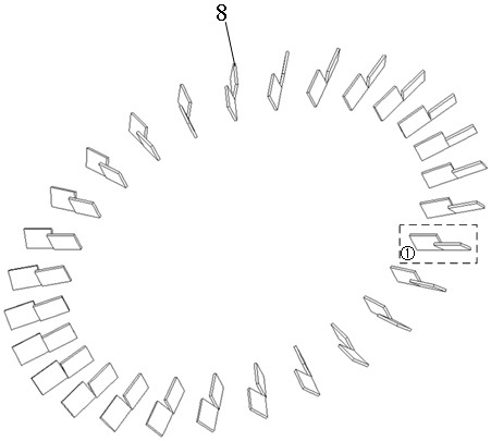
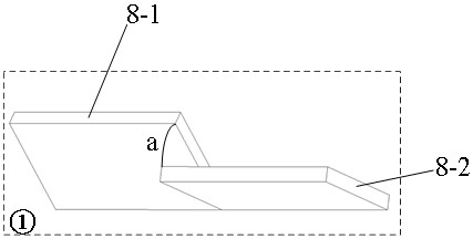
[0025] Embodiment 1: Combining figure 1 , figure 2 , image 3 , Figure 4 , Figure 5 , Image 6 , Figure 7 , Figure 8 Illustrating this embodiment, it includes a cooler 1, a stator support 2, a stator positioning rib 3, a stator iron core 4, a stator iron core radial ventilation groove 5, a rotor iron core 6, a rotor iron core radial ventilation groove 7, an electric axial flow-centrifugal Fan 8, centrifugal fan 9, rotor outer fixing plate 10, wind deflector 11, rotating shaft 12, stator pressure ring 13, stator pressure finger 14, stator end winding 15, rotor outer guard ring 16, rotor end winding 17, Inclined wind deflector 18, rotor pressure finger 19, rotor inner guard ring 20, casing 21, rotor single-stage axial fan 22, multi-stage sub-pressurized ventilation channel steel 23, wind guide teeth 24, rotor outer The radial vent 25 of the guard ring, the booster axial fan 26 and the ventilation hole 27, the stator core 4 is provided with a stator core radial ventil...

specific Embodiment approach 2

[0028] Specific implementation mode 2: Combining Figure 9 Describing this embodiment, the difference between this embodiment and Embodiment 1 is that the rotor outer shroud 16 is newly provided with a fourth-stage radial vent 25-4 and a fifth-stage radial vent 25-5 in the axial direction. , the contact area between the rotor outer shroud 16 and the cooling gas is increased, and the maximum temperature of the rotor outer shroud 16 is further reduced. Other components and connection relationships are the same as those in the first embodiment.

specific Embodiment approach 3

[0029] Specific implementation three: combination Figure 10 Describing this embodiment, the difference between this embodiment and the first embodiment is that the rotors on both sides of the rotating shaft 12 are adjusted to the single-stage axial flow fan 22 as a supercharging shaft composed of a static fan blade 26-1 and a moving fan blade 26-2. The flow fan 26 can ensure that the cooling gas enters the generator motor regularly through the static fan 26-1, which further reduces the ventilation loss of the cooling gas. Other components and connection relationships are the same as those in the first embodiment.


PUM


Abstract

The invention discloses a variable-speed pumped storage generator motor with an electric axial flow-centrifugal radial and axial pressurization end ventilation system, and relates to the field of motors. The problem that the temperature of an end component of an existing generator motor is high is solved. The air deflector is installed on the rotating shaft, the centrifugal fans are installed on the two sides of the rotor outer side fixing plate, the electric axial flow-centrifugal fans are installed on the two sides of the rotor pressing finger, axial flow blades in the electric axial flow-centrifugal fans can be electrically adjusted according to the rotating direction and the rotating speed, and the inclined air deflector is installed on the outer sides of the electric axial flow-centrifugal fans. N air guide teeth are arranged on the rotor outer protection ring in the circumferential direction, a first-stage radial ventilation opening, a second-stage radial ventilation opening and a third-stage radial ventilation opening are formed in the rotor outer protection ring in the axial direction, the rotor single-stage axial flow fan is installed on the rotating shaft, and multi-stage segmented supercharged ventilation channel steel is installed in a rotor radial ventilation duct. The ventilating and cooling capacity of the end part of the generator motor is improved, the structure is simple, and implementation is convenient.

Description

technical field [0001] The invention relates to a variable-speed pumped-storage generator motor with an electric axial flow-centrifugal radial axial pressurization end ventilation system, and belongs to the field of motors. Background technique [0002] With the continuous development of the national economy, electricity has increasingly become an important energy and material basis for various industries in society. The large-scale construction of pumped storage power stations can effectively promote the consumption of new energy, reduce the overall energy consumption of the system, and ensure the safe and stable operation of the power grid. The pumped-storage generator motor, which is a key component of the power station, is almost all of the rotor DC excitation constant-speed pumped-storage generator motor. The conventional pumped-storage generator motor is in a pumped-storage power station with a large water head change. It is not enough to meet the urgent needs of larg...

Claims


Application Information

Patent Timeline
Patent Type & Authority Applications(China)
IPC IPC(8): H02K9/18H02K1/20H02K1/32
CPCH02K9/18H02K1/20H02K1/32Y02E60/16
Inventor 韩继超戚海铭孙玉田董桀辰刘玉飞滕明轩邱家玉王教宇
Owner HARBIN UNIV OF SCI & TECH
Learn More