
Power supply cable and power supply method thereof

A power supply method and electric cable technology, applied in the field of power supply cable and its power supply

Pending Publication Date: 2022-08-02
HUAWEI TECH CO LTD
View PDF0 Cites 0 Cited by
  • Summary
  • Abstract
  • Description
  • Claims
  • Application Information

AI Technical Summary

Problems solved by technology

[0006] The embodiment of the present application provides a power supply cable and its power supply method, which are used to solve the problem of how to meet the power supply demand of the load end

Method used


Image

  • Power supply cable and power supply method thereof
  • Power supply cable and power supply method thereof
  • Power supply cable and power supply method thereof

Examples


Embodiment 1

[0083] like Figure 4a As shown, the power supply method of the power supply cable 10 includes:

[0084] During the power supply process, the current threshold detection circuit detects the energization current (load current) between the input terminal I and the output terminal O, compares the current signal with the first threshold current, and outputs the comparison result.

[0085] There are two comparison results, one is that the current signal is greater than the first threshold current, and the other is that the current signal is less than or equal to the first threshold current.

[0086] When the current signal is greater than the first threshold current, the first control signal output by the control circuit 12 controls the booster circuit 14 to turn on.

[0087] The booster circuit 14 is turned on under the control of the first control signal, and increases the voltage value of the electrical signal output by the supplementary battery 13 to the first set value, and t...

Embodiment 2

[0110] The difference between the second embodiment and the first embodiment is that the electrical signal threshold detection circuit is a voltage threshold detection circuit.

[0111] like Figure 5a As shown, the power supply method of the power supply cable 10 includes:

[0112] During the power supply process, the voltage threshold detection circuit detects the voltage signal (power supply voltage) between the input terminal I and the output terminal O, compares the voltage signal with the first threshold voltage, and outputs the comparison result.

[0113] There are two types of comparison results, one is that the voltage signal is less than the first threshold voltage, and the other is that the voltage signal is greater than or equal to the first threshold voltage.

[0114] When the voltage signal is less than the first threshold voltage, the first control signal output by the control circuit 12 controls the booster circuit 14 to turn on.

[0115] The booster circuit ...


PUM


Abstract

The embodiment of the invention provides a power supply cable and a power supply method thereof, relates to the technical field of power supply, and is used for solving the problem of how to meet the power supply requirement of a load end. The power supply cable comprises an input end and an output end; the electric signal threshold detection circuit is coupled with the input end and the output end and is used for detecting an electric signal between the input end and the output end, comparing the electric signal with a first threshold and outputting a comparison result; the control circuit is coupled with the electric signal threshold detection circuit and is used for outputting a first control signal according to the comparison result; the charging battery is used for auxiliary power supply; and the booster circuit is coupled with the charging battery and the control circuit and is used for controlling whether the voltage value of the electric signal output by the charging battery is increased to a first set value or not under the control of the first control signal and transmitting the voltage value to the output end.

Description

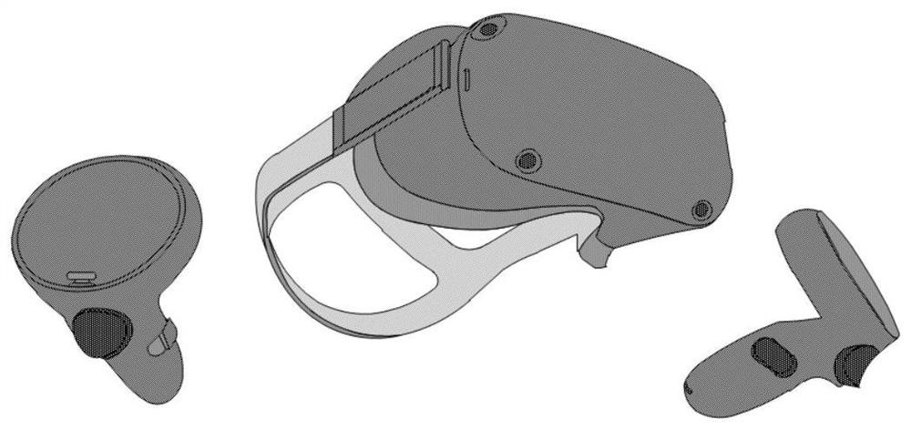
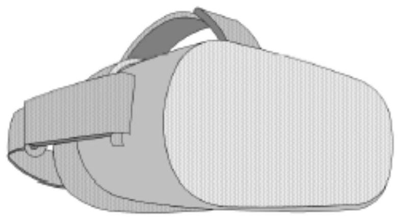
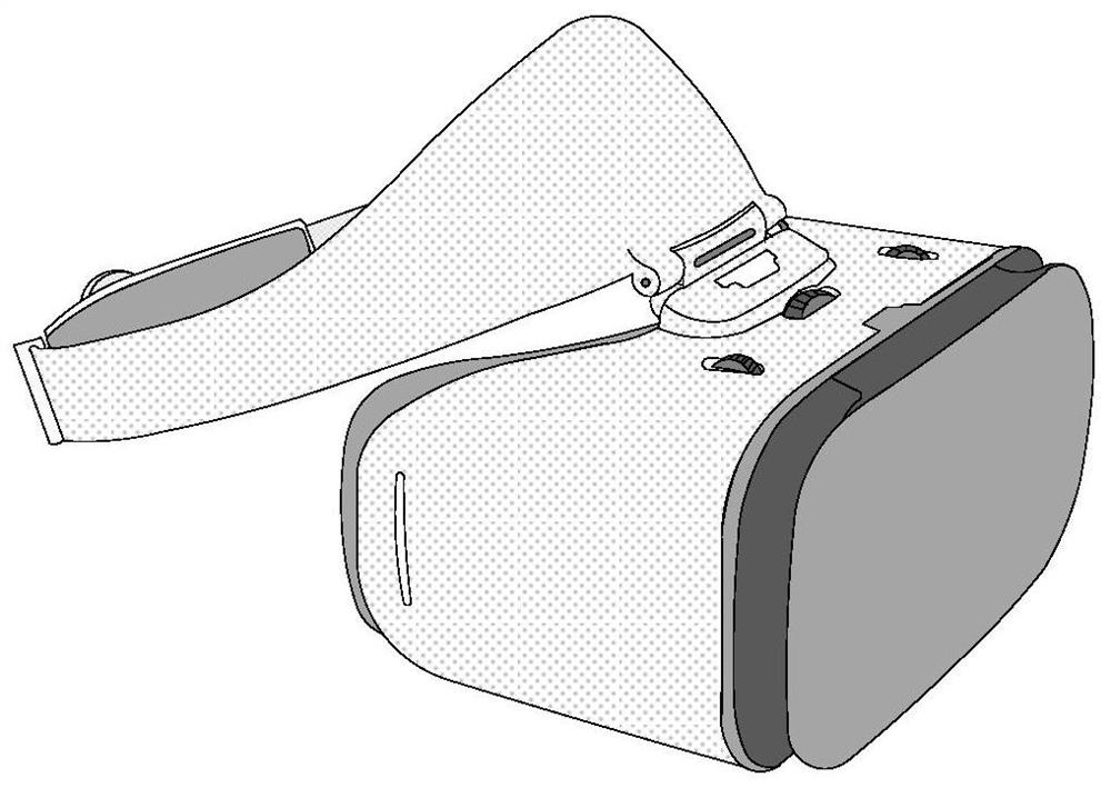
technical field [0001] The present application relates to the technical field of power supply, and in particular, to a power supply cable and a power supply method thereof. Background technique [0002] In recent years, virtual reality (VR) devices have once set off a technological upsurge, and many forms of VR devices have appeared on the market. VR equipment mainly includes two major modules: display and processing. According to whether display and processing are on the same component, VR equipment is divided into two categories: VR equipment in the form of an all-in-one machine (display and processing are completed by the VR equipment) or discrete form of VR equipment. VR equipment. [0003] Different forms of VR devices have different power supply methods. There are self-contained battery power supply, power supply through personal computer (PC) or mobile phone, two types of integrated power supply, and power supply by external power supply equipment. like Figure 1a ...

Claims


Application Information

Patent Timeline
IPC IPC(8): H02J7/00H02J9/06
CPCH02J7/0063H02J7/0068H02J9/061Y02T10/7072
Inventor 王远国郭奇雨
Owner HUAWEI TECH CO LTD
Learn More