
Automatic design method for optical filter film system

A design method and film system design technology, applied in optics, optical components, instruments, etc., can solve the problems of calculation results of 0, 1 or infinity, large amount of calculation, and inability to optimize the structure of the filter film system, etc., to shorten the design cycle, simplified design process, and easy-to-learn effects

Pending Publication Date: 2022-08-02
CENT SOUTH UNIV
View PDF8 Cites 0 Cited by
  • Summary
  • Abstract
  • Description
  • Claims
  • Application Information

AI Technical Summary

Problems solved by technology

[0005] (1) When using parameter scanning or optimization algorithms based on gradient information for optimization, it is easy to fall into a local optimal solution
[0006] (2) In the existing design method of optical filter film system, the design of the initial film system still needs to rely on the experience of the designer, and it is necessary to have a certain understanding of the influence of the structural parameters of the film system on the optical characteristics, the design cycle is long, and It is difficult for beginners to design directly
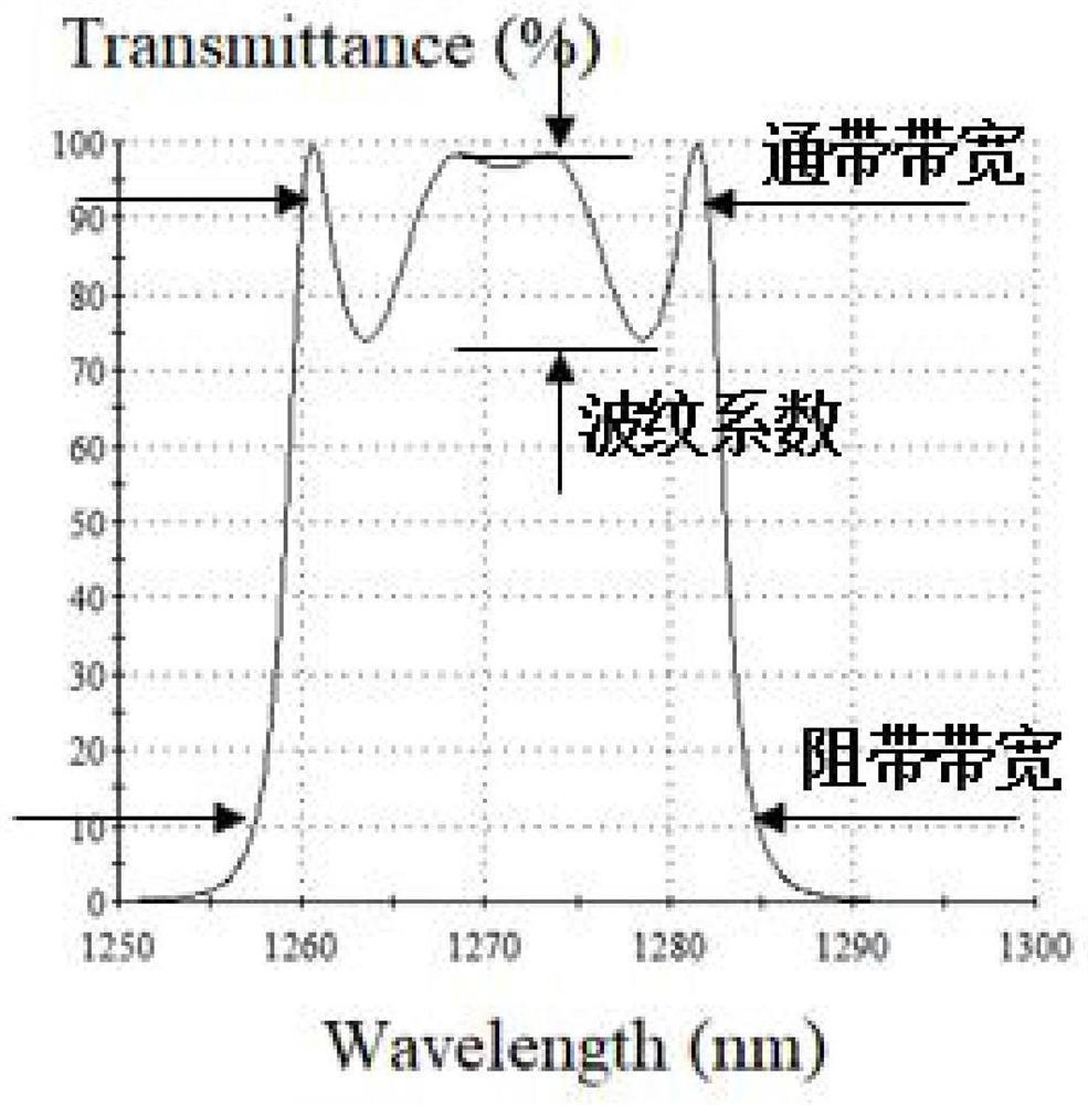
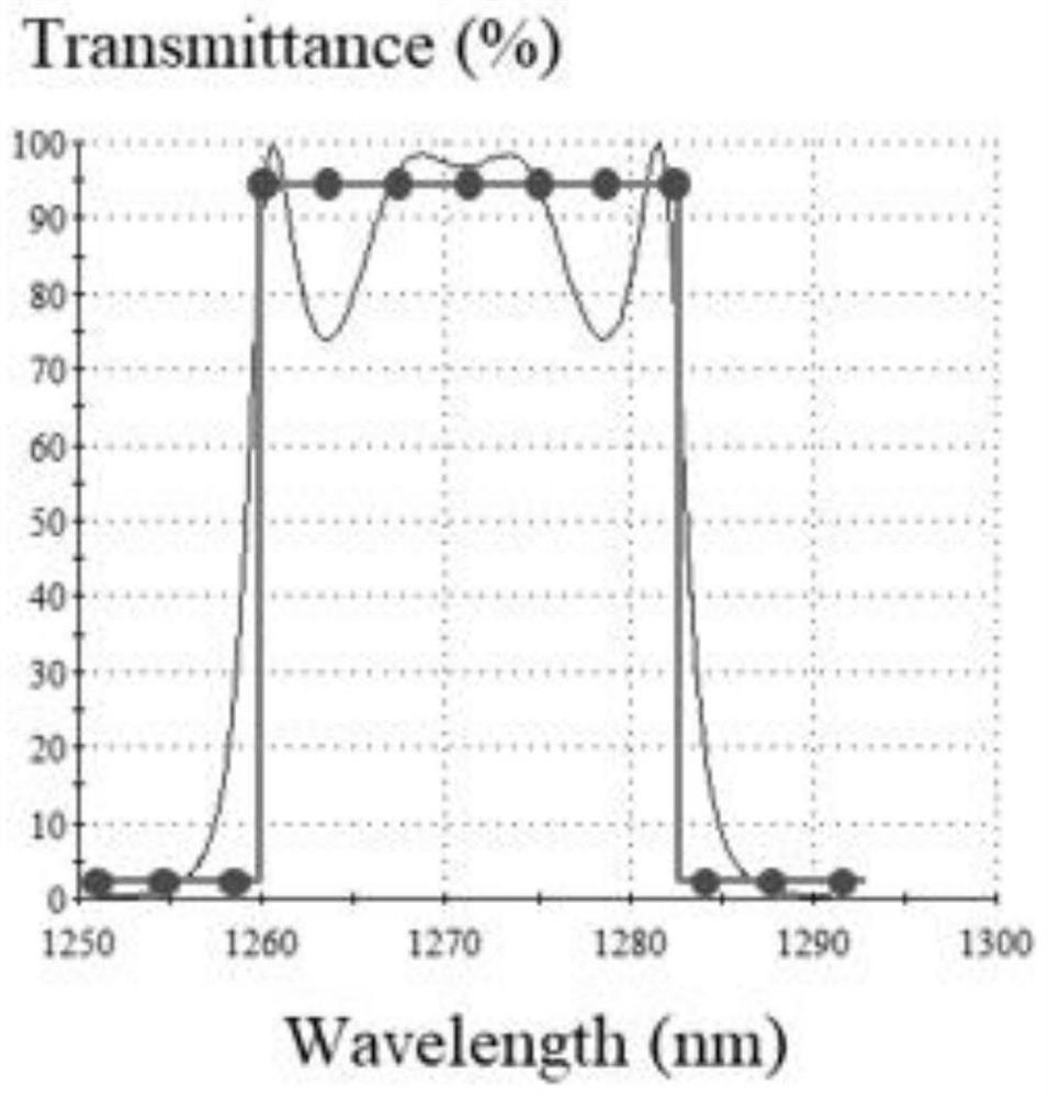
[0007] (3) The currently used evaluation function is generally: ψ(s i ,w i ,P)=ω ξ (10ξ) 2 +ω ε (1-ε) 2 , that is, from the two evaluation index values ​​of rectangularity ε and waviness coefficient ξ to comprehensively evaluate the quality of the optical characteristic curve of the filter, the amount of calculation is large
[0008] (4) In the actual calculation process of the rectangularity, there is usually a limitation of the calculation range of a certain wavelength, and the bandwidth corresponding to the specific loss calculated within the wavelength limit range may not match the actual value, resulting in the calculation result of the rectangularity Phenomena such as 0, 1 or infinity appear, causing computer calculation errors
[0009] (5) Since the magnitude of the rectangularity and the ripple coefficient are different, the corresponding weight values ​​need to be modified and debugged repeatedly, and the possible extreme values ​​of the evaluation function cannot be accurately predicted. When using the genetic algorithm for optimization, if the traditional evaluation function is directly If the function is used as a fitness value, the fitness value may be negative, which will lead to an error in the iteration of the genetic algorithm
[0010] (6) The genetic algorithm currently used has not been combined with the design method of the bandpass filter film system, or made targeted improvements to the change law of its optical characteristics, and cannot better understand the film system structure of the filter optimized for a specific design

Method used


Image

  • Automatic design method for optical filter film system
  • Automatic design method for optical filter film system
  • Automatic design method for optical filter film system

Examples


Embodiment Construction

[0055] The technical solutions in the embodiments of the present invention will be clearly and completely described below with reference to the accompanying drawings in the embodiments of the present invention. Obviously, the described embodiments are only a part of the embodiments of the present invention, but not all of the embodiments. Based on the embodiments of the present invention, all other embodiments obtained by those of ordinary skill in the art without creative efforts shall fall within the protection scope of the present invention.

[0056] see Figure 1-4 , the embodiments provided by the present invention:

[0057] An automatic design method for a filter film system, the automatic design method for a filter film system comprises the following steps:

[0058] S1. Determine the solution space

[0059] The film system design of the wavelength division multiplexing filter adopts a regular film system structure, and its main structural parameters include the number...


PUM


Abstract

The invention relates to the technical field of optical filter film systems, in particular to an automatic design method for an optical filter film system, which comprises the following steps: S1, determining a solution space, S2, adjusting a central wavelength, S3, encoding structural parameters, S4, generating an initial population, S5, calculating optical characteristics, S6, calculating bandwidth and passband ripples, and S7, adapting an operator process. According to the automatic design method for the optical filter film system, the film system design work of an optical filter has the advantages of global optimization, easy programming implementation, small calculation amount, good optimization effect, automatic design and simple and convenient operation, and the film system design work of the optical filter is enabled to have the advantages of global optimization, easy programming implementation, small calculation amount, automatic design and simple and convenient operation.

Description

technical field [0001] The invention relates to the technical field of filter film systems, in particular to an automatic design method for filter film systems. Background technique [0002] The optical properties of the optical filter depend on the material, thickness and arrangement of the film layer, and the design of the optical filter is to optimize the structure of the film layer. [0003] The existing filter film system design methods are generally divided into two types. One is to rely on the knowledge of thin film optics and combine the designer's experience to design. Usually, it is based on a specific film system structure, combined with the equivalent layer method, vector illustration method, etc. Using analytical design methods such as the effective interface method to manually design and adjust the film system, this method is time-consuming and labor-intensive, and requires a high degree of the designer's basic knowledge of film optics and film system design ex...

Claims


Application Information

Patent Timeline
IPC IPC(8): G02B27/00
CPCG02B27/0012
Inventor 郑煜谢万胜成杰谢星浩段吉安
Owner CENT SOUTH UNIV
Learn More