Eureka AIR delivers breakthrough ideas for toughest innovation challenges, trusted by R&D personnel around the world.

Current output mechanism and test device

An output mechanism and current technology, applied in the direction of measuring devices, transportation and packaging, electric vehicles, etc., can solve the problems of high power input power and difficulty in effectively reducing the inductance of the loop, so as to achieve power reduction, reduce resistance and inductance, and reduce The effect of inductive resistance

Pending Publication Date: 2022-08-02
CHINA ELECTRIC POWER RES INST
View PDF0 Cites 0 Cited by
  • Summary
  • Abstract
  • Description
  • Claims
  • Application Information

AI Technical Summary

Problems solved by technology

[0004] However, under strong current, the resistance of the loop (that is, the internal resistance of the current booster coil, the resistance of the output copper bar, the test output and the cable resistance of the test output and the connecting terminal) can be reduced by increasing the cross-sectional area of ​​the output copper bar, so that The resistance of the loop can be controlled within tens of microohms; and the inductance of the loop is difficult to effectively reduce because of the need to provide an output detection loop. Even if it is less than 1 microhenry, it can generate hundreds of microohms of output loop inductance, resulting in The required power input apparent power is higher

Method used


Image

  • Current output mechanism and test device
  • Current output mechanism and test device

Examples


Embodiment Construction

[0020] The present invention will be further described in detail below with reference to the accompanying drawings.

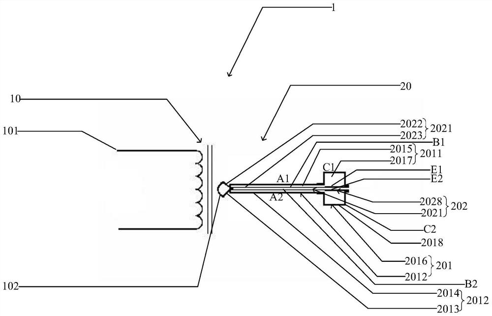
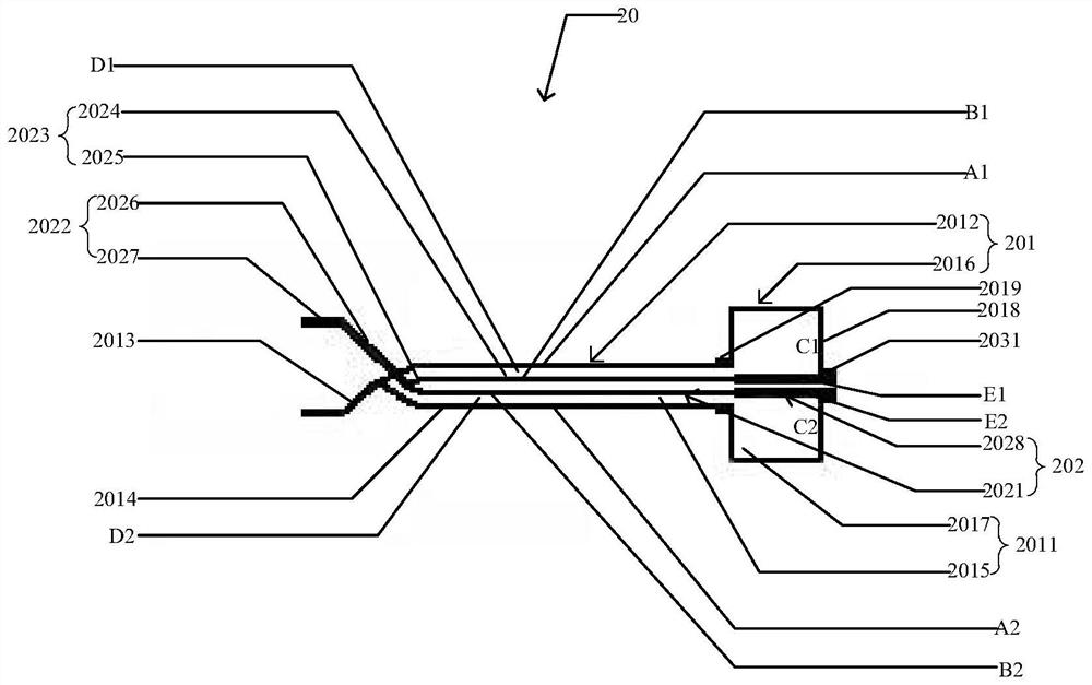
[0021] refer to figure 1 and figure 2 , is a test device 1 disclosed in the present invention, comprising a current booster 10 and a current output mechanism 20; the input terminal 101 of the current booster 10 is connected to an external power supply, and the output terminal 102 of the current booster 10 is connected to the current output The mechanism 20 is connected, and the end of the current output mechanism 20 away from the current booster 10 is used to connect with the device to be tested; during use, the small current output by the power supply is increased into a large current through the current booster 10, and the large current passes through the current output mechanism. 20 is input to the device under test to perform the power frequency short-time overcurrent withstand test of the device under test.

[0022] The current output mechanism 20 inclu...


PUM


Abstract

The invention relates to a current output mechanism and a test device. The test device comprises a current booster and the current output mechanism. An input terminal of the current booster is connected with an external power supply, and an output terminal of the current booster is connected with the current output mechanism; the current output mechanism comprises a first output unit and a second output unit, a containing cavity is defined by the first output unit, the output end of the second output unit is inserted into the containing cavity, the output end of the second output unit is connected with the inflow end of the first output unit, and the first output unit and the second output unit jointly form a closed loop; the second output unit is used for being matched with the first output unit to shunt the current in the closed loop; by arranging the first output unit and the second output unit, current shunting in the closed loop is realized, so that resistance and inductance in the closed loop are reduced, inductive reactance of the closed loop is further reduced, and apparent power of the power supply is reduced.

Description

technical field [0001] The invention relates to the technical field of current output test devices, in particular to a current output mechanism and a test device. Background technique [0002] At present, there is a power frequency short-time overcurrent withstand test in the testing items of some power electronic equipment such as current monitoring devices, current transformers and other products, and the test current is generally high. In a high current loop, the inductive reactance of cables or copper bars has a great influence. [0003] The traditional high current output device includes power input, current booster, output copper bar, connection terminal and test output piece. The power input improves the current output capability through the current booster, the output end of the current booster is connected to the connection terminal through the output copper bar, and the end of the connection terminal away from the output copper bar is connected to the test output ...

Claims


Application Information

Patent Timeline
Patent Type & Authority Applications(China)
IPC IPC(8): G01R35/00G01R35/02
CPCG01R35/007G01R35/02Y02T90/14
Inventor 王聪张蓬鹤赵兵陈昊杨艺宁宋如楠杨柳
Owner CHINA ELECTRIC POWER RES INST
Why Eureka
Eureka Blog
Learn More