
Mechanical experiment equipment and use method thereof

A kind of experimental equipment and mechanical technology, applied in aerodynamic test, machine/structural component test, instrument, etc., can solve the problems that the wind direction cannot be adjusted, the model layout is cumbersome to load and unload, and the pressure data cannot be obtained directly.

Pending Publication Date: 2022-08-02
GUANGDONG INST OF SCI & TECH
View PDF1 Cites 0 Cited by
  • Summary
  • Abstract
  • Description
  • Claims
  • Application Information

AI Technical Summary

Problems solved by technology

But there are the following problems: 1. The wind direction cannot be adjusted; 2. The pressure data cannot be obtained directly; 3. The model layout is cumbersome to load and unload

Method used


Image

  • Mechanical experiment equipment and use method thereof
  • Mechanical experiment equipment and use method thereof
  • Mechanical experiment equipment and use method thereof

Examples


Embodiment 1

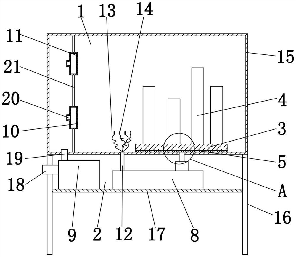
[0039] Example 1: To test the stress situation of buildings in different wind directions and wind conditions, and when multiple buildings are arranged differently, the stress situation in the same wind direction and wind force is carried out according to the following steps:

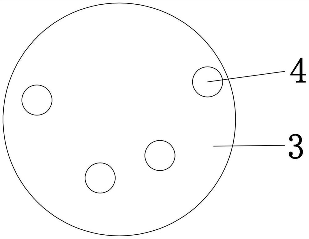
[0040] Step 1. Insert multiple models 4 on the soft board 3 according to the design scheme;

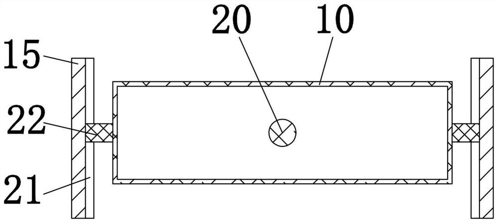
[0041] Step 2: Connect the air outlet duct 19 of the fan 9 to the interface 20 of the air distribution box 10 through a pipeline;

[0042] Step 3. Pull out the pressure sensor 14 and fix it on the model 4;

[0043] Step 4: Set the wind speed according to the design scheme, and adjust the height of the blower by adjusting the height of the air distribution box 10 to simulate the wind environment;

[0044] Step 5. Obtain pressure data;

[0045] Step 6: Adjust the wind speed and height, turn the rotary plate 5 at the same time, adjust the direction of the model 4, and then simulate different directions to obtain ...

Embodiment 2

[0048] Embodiment 2: Test the stress condition of the automobile model in different wind directions and wind conditions, as well as the fluid structure test of the automobile model, and test the wind resistance of different automobile structures according to the following steps,

[0049] Step 1. Insert the car model on the soft board 3 according to the method;

[0050] Step 2: Connect the air outlet duct 19 of the fan 9 to the interface 20 of the air distribution box 10 through a pipeline;

[0051] Step 3. Pull out the pressure sensor 14 and fix it on the model 4;

[0052] Step 4: Set the wind speed according to the design scheme, and adjust the height of the blower by adjusting the height of the air distribution box 10 to simulate the wind environment;

[0053] Step 5. Obtain pressure data;

[0054] Step 6: Adjust the wind speed and height, turn the rotary plate 5 at the same time, adjust the direction of the model 4, and then simulate different directions to obtain pressure ...


PUM


Abstract

The invention discloses mechanical experiment equipment and a using method thereof.The mechanical experiment equipment comprises an experiment area and an electric control area, a soft plate is arranged in the experiment area, a plurality of models are movably inserted into the soft plate, the lower end of the soft plate is connected with a rotating plate, the lower end of the rotating plate is connected with a rotating shaft, the rotating shaft penetrates through the experiment area to be connected to a rotating device arranged in the electric control area, and the rotating device is connected to a controller; the controller is arranged in an electric control area, the electric control area is further provided with a draught fan, and the draught fan is connected to the air distribution box through a pipeline. The method has the advantages that the model is placed on the soft board, and the model can be quickly assembled and disassembled; a pressure sensor is arranged inside, and the pressure sensor is placed and fixed on the model, so that pressure data can be quickly obtained; air is discharged through the air distribution box, the air distribution box can move up and down, the air outlet height is adjusted, the rotating plate is matched to drive the model to rotate, and the environment is simulated more truly.

Description

technical field [0001] The invention relates to a mechanical experimental device and a method of using the same, belonging to the technical field of experimental devices. Background technique [0002] The patent No. 202111441381.3 discloses a high wind environment simulation test box based on computational fluid dynamics, which adjusts the size of the air outlet by adjusting the components, obtains different wind speeds under the same air volume, and then according to the different wind speeds or different wind speeds. Simulation data to ensure the accuracy of the simulation data, thereby ensuring the rationality of architectural or urban planning. However, there are the following problems: 1. The wind direction cannot be adjusted; 2. The pressure data cannot be directly obtained; 3. The model layout is cumbersome to load and unload. SUMMARY OF THE INVENTION [0003] The technical problem to be solved by the present invention is to provide a mechanical experimental equipm...

Claims


Application Information

Patent Timeline
Patent Type & Authority Applications(China)
IPC IPC(8): G01M9/00G01M9/08
CPCG01M9/00G01M9/08
Inventor 赖兴余何宁发刘洪明赖永欣陈镇秋胡红坡王辉曹原菲欧芷嫣伍世平李家成宋永坚李子朗何嘉俊
Owner GUANGDONG INST OF SCI & TECH
Learn More