


Quick Research
Generate reliable direction feasibility study reports for your R&D in just a few steps.

Technical Q&A
Discover and master advanced knowledge NOW. Basics, ideas, possibilities, all at once.

Find Solutions
As an expert in R&D theories, this can generate solutions to your technical problems instantly.

Evaluate Feasibility
Analyze your overall solution with one click, know your potential R&D risks in advance.

Monitor Landscape
Get weekly tech updates, stay abreast of the latest tech innovations and key insights.
Cylindricity measuring device
A measuring device, cylindricity technology, applied in measuring devices, using fluid devices, using optical devices, etc., can solve problems such as parts stuck
- Summary
- Abstract
- Description
- Claims
- Application Information
AI Technical Summary
Problems solved by technology
Method used
Image

Examples
Embodiment 1
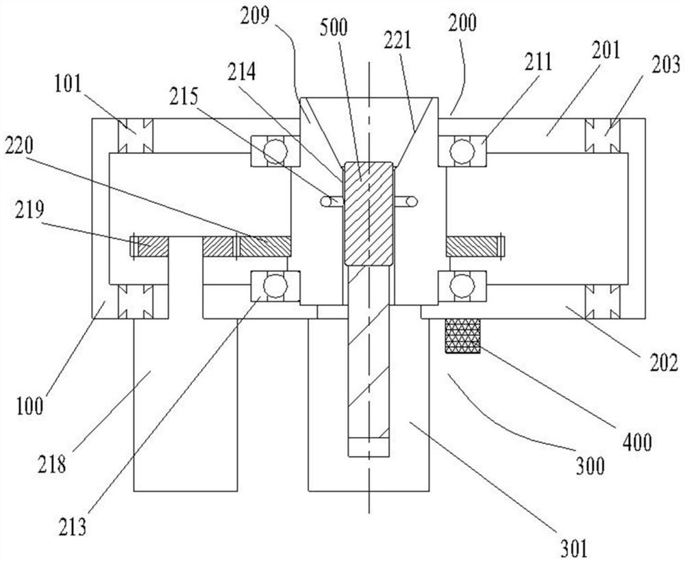
[0047] like figure 1 As shown, the cylindricity measuring device provided in this embodiment includes a workbench 300, and the workbench 300 includes a base body 100 and an installation frame 200. The installation frame 200 is installed on the base body 100 through elastic connectors, and a scanning structure is installed on the installation frame 200. 209. Linear drive mechanism and rotary drive mechanism, the scanning structure 209 is provided with a part accommodating hole 214, the side wall of the part accommodating hole 214 is provided with a measuring head, and the measuring head is connected with the data processing device 400.
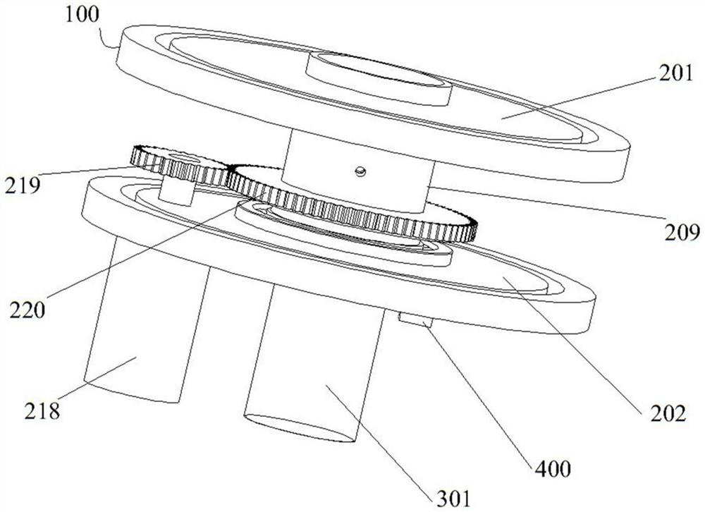
[0048] In this embodiment, as figure 1 and figure 2 As shown, the base body 100 is a cylindrical structure, the mounting frame 200 includes an upper frame body 201 and a lower frame body 202, the upper frame body 201 and the lower frame body 202 are both annular plate-shaped structures, and the elastic connecting member is an elastic rod 203....
Embodiment 2
[0056] The difference between this embodiment and Embodiment 1 is that, in Embodiment 1, the elastic connecting member is an elastic rod. In this embodiment, the elastic connector is a spring, the mounting frame is supported on the base by the spring, one end of the spring is connected and fixed with the mounting frame, and the other end of the spring is connected and fixed with the base. When the force is applied, the mounting seat can transmit the force to the spring, and the spring is deformed by the force, so that the mounting bracket can be deflected to the position where the part receiving hole is aligned with the part to be measured, and when the part to be measured enters the part receiving hole Afterwards, the spring can also drive the mounting frame to return to the initial position by its own elastic force.
Embodiment 3
[0058]The difference between this embodiment and Embodiment 1 is that in Embodiment 1, the elastic connecting pieces extend laterally and are arranged in a plurality of circumferential directions of the mounting frame, and the two ends of each elastic connecting piece are respectively connected with the seat body and the mounting frame. Connection is fixed. In this embodiment, the elastic connecting pieces are arranged vertically extending, and the number of elastic connecting pieces is two. The two elastic connecting pieces are arranged on both sides of the part accommodating hole, and the upper and lower ends are respectively supported and fixed to the mounting frame and the base. Ensure that when the robot exerts a force on the mounting frame through the part to be tested, the acting force can apply sufficient yaw moment to the two elastic connectors. After the two elastic connectors are deformed, the mounting bracket can also be swayed to the part accommodating hole and the...
PUM
 Abstract
Description
Claims
Application Information
 - R&D Engineer
- R&D Manager
- IP Professional
- Industry Leading Data Capabilities
- Powerful AI technology
- Patent DNA Extraction
Browse by: Latest US Patents, China's latest patents, Technical Efficacy Thesaurus, Application Domain, Technology Topic, Popular Technical Reports.
© 2024 PatSnap. All rights reserved.Legal|Privacy policy|Modern Slavery Act Transparency Statement|Sitemap|About US| Contact US: help@patsnap.com