
Gear interlocking mechanism for transmission and manual transmission assembly

A technology of interlocking mechanism and transmission, applied in mechanical equipment, transmission control, components with teeth, etc., can solve the problem of vehicle layout space occupation, increased axial space cost, and interlocking mechanism cannot be arranged in transmissions, etc. problem, to achieve the effect of expanding compatibility

Pending Publication Date: 2022-08-02
WUHU WANLIYANG TRANSMISSION CO LTD
View PDF0 Cites 0 Cited by
  • Summary
  • Abstract
  • Description
  • Claims
  • Application Information

AI Technical Summary

Problems solved by technology

[0003] Specifically, the existing manual transmission gear interlock mechanism can be designed in the axial space, and the problems caused by the reverse gear can be solved through the interlock function. However, as users improve the performance of the reverse gear, such models They are all required to increase the reverse gear pre-synchronization function. In terms of the added function alone, the increased axial space has occupied the spare layout space of the vehicle, and the interlock mechanism will not be able to be arranged on the transmission, and even if the vehicle layout space Allowed, the cost increase brought by the increased axial space also brings a burden on the enterprise

Method used


Image

  • Gear interlocking mechanism for transmission and manual transmission assembly
  • Gear interlocking mechanism for transmission and manual transmission assembly
  • Gear interlocking mechanism for transmission and manual transmission assembly

Examples


Embodiment Construction

[0019] Below with reference to the accompanying drawings, through the description of the embodiments, the specific embodiments of the present invention will be described in further detail, the purpose is to help those skilled in the art to have a more complete, accurate and in-depth understanding of the concept and technical solutions of the present invention, and contribute to its implementation.

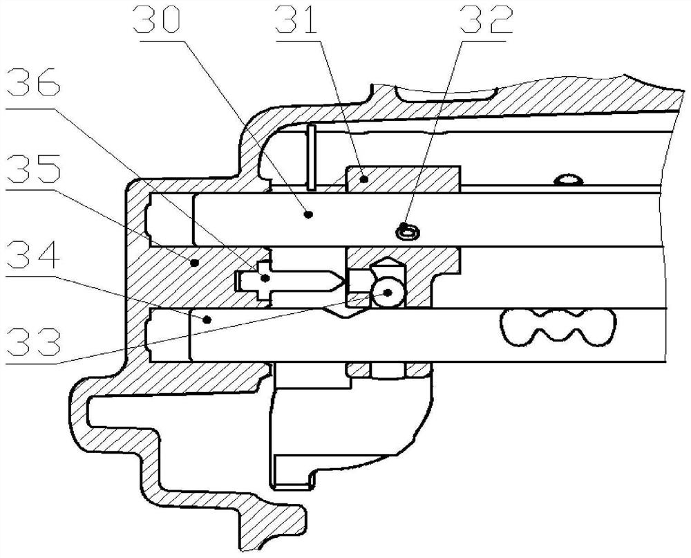
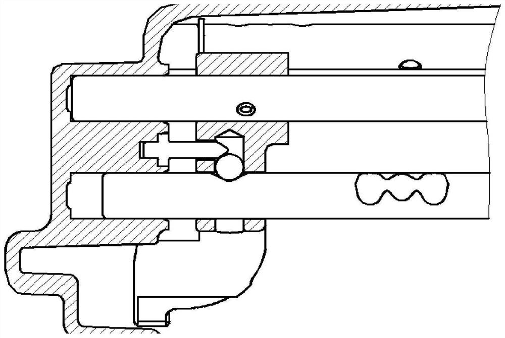
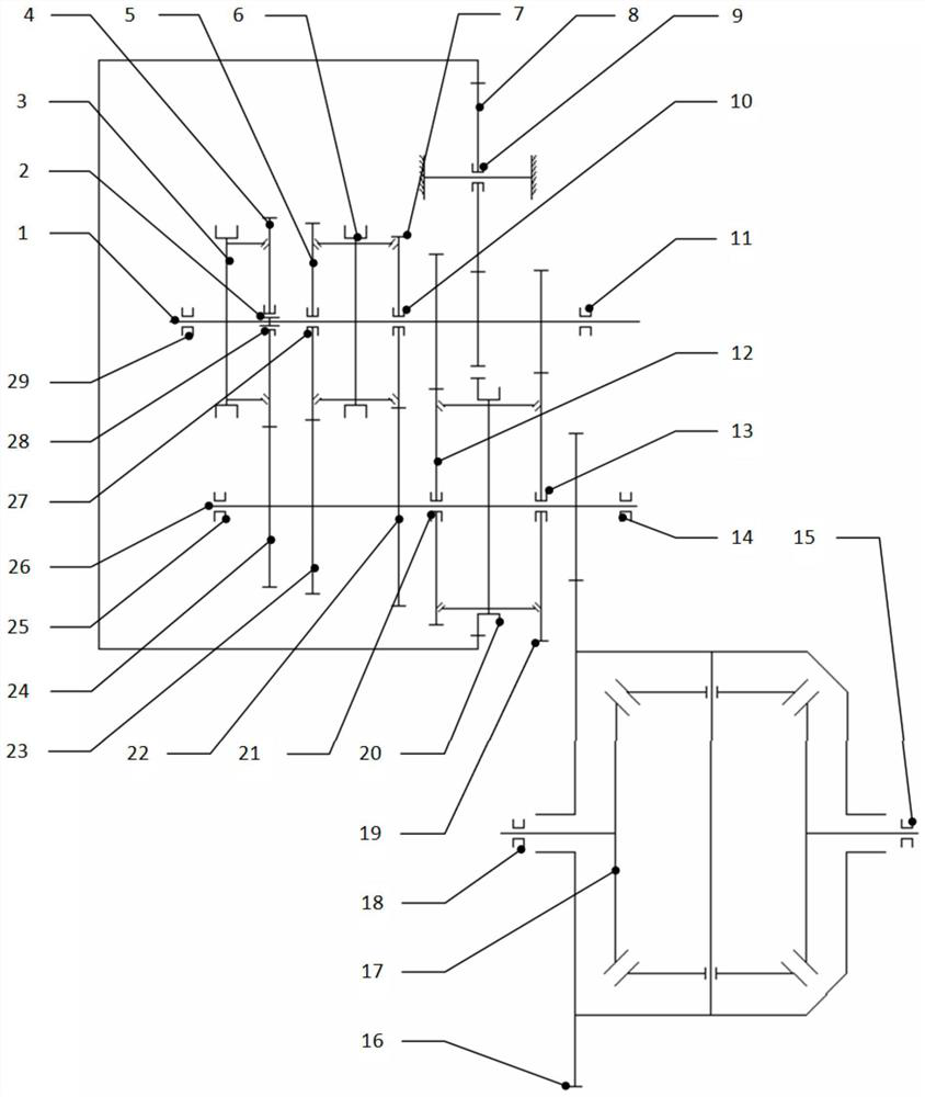
[0020] like figure 1 and figure 2 As shown, the present invention provides a gear interlocking mechanism for a transmission, which includes a movable locking member 33 arranged on the 5 / reverse shift fork 31 and a locking member 33 for moving the 5 / reverse shift fork 31 to reverse. When in the gear position, push the locking member 33 to insert the interlocking pin 36 in the locking groove provided on the 1 / 2 gear shift fork shaft 34; Perpendicularly, after the locking member 33 is inserted into the locking groove, the 1 / 2 gear fork shaft 34 stops moving in the axial direction, ...


PUM


Abstract

The gear interlocking mechanism comprises a locking piece and an interlocking pin shaft, wherein the locking piece is movably arranged on a fifth / reverse gear shifting fork, and the interlocking pin shaft is used for pushing the locking piece to be embedded into a locking groove formed in a 1 / 2 gear shifting fork shaft when the fifth / reverse gear shifting fork moves to the reverse gear position. The moving direction of the locking piece is perpendicular to the axial direction of the 1 / 2 gear shifting fork shaft, and after the locking piece is embedded into the locking groove, the 1 / 2 gear shifting fork shaft stops moving in the axial direction. According to the gear interlocking mechanism for the transmission, a gear interlocking scheme is changed into a vertical part interlocking mode, the existing arrangement space can be effectively utilized, on the premise that the interlocking function between gears is achieved, the appearance size of parts is not increased, products can better adapt to the whole vehicle space to be arranged, and the matching performance of the products in the whole vehicle is expanded. The invention further discloses a manual transmission assembly.

Description

technical field [0001] The invention belongs to the technical field of transmissions, and in particular, the invention relates to a gear interlocking mechanism for transmissions and a manual transmission assembly. Background technique [0002] In the existing manual transmission gear interlock mechanism, the reverse gear arrangement is in the form of idler slippage, and the second stage intermediate gear of the reverse gear borrows the 1 / 2 gear synchronizer sleeve as the transmission part. This structure makes the reverse gear slip. When the gear is working, the gear sleeve has a certain axial force to push the direction of the second gear, which will form a certain pressure on the second gear synchronizing ring. In the reverse gear structure design of this type of transmission, the reverse gear shift fork shaft and the 1 / 2 gear shift fork shaft are designed with a return interlock mechanism in the axial space, and the interlock mechanism limits the 1 / 2 gear shift after the ...

Claims


Application Information

Patent Timeline
Patent Type & Authority Applications(China)
IPC IPC(8): F16H63/36
CPCF16H63/36
Inventor 李德龙郑前文董宾康军波汪邦勇
Owner WUHU WANLIYANG TRANSMISSION CO LTD
Learn More