
Fixing frame of plane display module

A flat display and fixed frame technology, applied in optics, instruments, nonlinear optics, etc.

Active Publication Date: 2005-08-24
AU OPTRONICS CORP
View PDF0 Cites 4 Cited by
  • Summary
  • Abstract
  • Description
  • Claims
  • Application Information

AI Technical Summary

Problems solved by technology

However, since the appearance size of the flat display module is getting closer to the size of the actual display panel, the complicated and oversized fixing frame will not be accepted by the users and the manufacturers or designers of the flat display module.

Method used


Image

  • Fixing frame of plane display module
  • Fixing frame of plane display module

Examples


Embodiment Construction

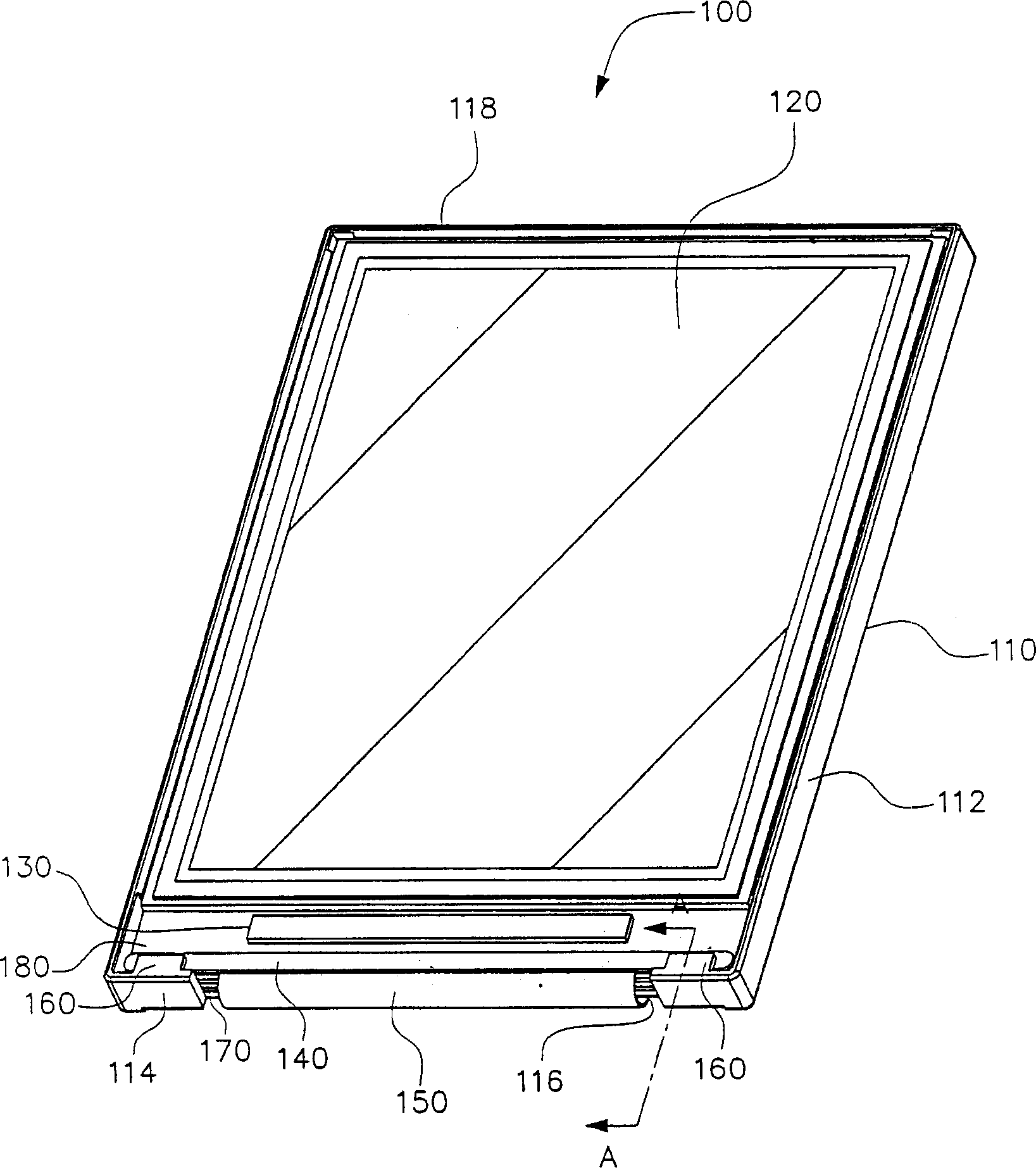
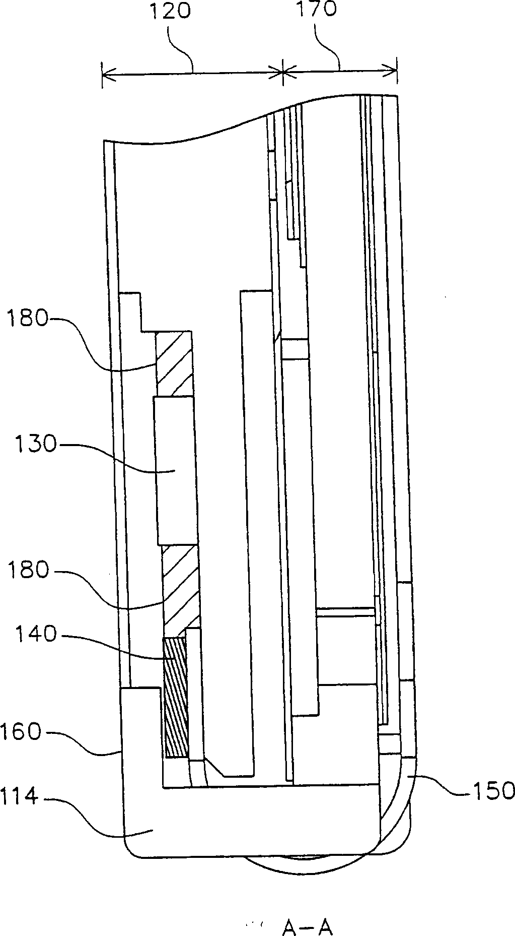
[0014] The fixed frame of the flat display module of the present invention not only does not need to increase the appearance size of the fixed frame, but also is convenient to manufacture. With the setting of the buffer strip, it can protect the panel and effectively control the relative size of the panel and the fixed frame without affecting the flat display. Module installation and fabrication. The following will clearly illustrate the spirit of the present invention with illustrations and detailed descriptions. After those skilled in the art understand the preferred embodiments of the present invention, they can be changed and modified by the techniques taught in the present invention without departing from the present invention. The spirit and scope of the invention.

[0015] refer to Figure 1A , which is a schematic diagram of a liquid crystal display module, and is a preferred embodiment of the flat display module fixing frame of the present invention, and Figure 1B I...


PUM


Abstract

This invention discloses a retaining framework of the two-dimensional display. This retaining framework has two side bulkheads, one upper bulkhead, at least one lower bulkhead and at least one lug. The side, the upper and the lower bulkheads form the space that contains a two-dimensional display face plate. The lug is above the lower bulkhead and couples the face plate in the retaining framework to avoid the face plate being left by a curled soft base plate. There is at least one buffering protective bar between the lug and the face plate to avoid the face plate contacting the lug directly and improve the retaining effect of the face plate.

Description

technical field [0001] The invention relates to a flat display module fixing frame, in particular to a flat display module fixing frame with a lug structure. Background technique [0002] As the information and communication industries continue to innovate, the liquid crystal display (liquid crystal display; LCD) market is booming. Liquid crystal displays have the advantages of high image quality, small size, light weight, low driving voltage, and low power consumption, so they are widely used in personal digital assistants (personal digital assistants; PDAs), mobile phones, camcorders, notebooks, etc. Consumer communication or electronic products such as computers, desktop monitors, car monitors, and projection TVs. Coupled with the rapid development of integrated circuit (integrated circuit; IC) industry and liquid crystal display manufacturing technology, these consumer communication or electronic products are also developing towards the trend of light, thin, short and s...

Claims


Application Information

Patent Timeline
Patent Type & Authority Applications(China)
IPC IPC(8): G02F1/1333G09F9/00G12B9/00
Inventor 蔡宜桦宋光涛
Owner AU OPTRONICS CORP
Learn More