Automatic detection, automatic dispensing and automatic sorting device for LED lamp beads arranged in array mode
A technology of LED lamp beads and array arrangement, which is applied to the surface coating liquid device, lamp testing, sorting, etc., can solve the problem of low glue dispensing efficiency, avoid secondary repair use, and reduce manual labor , the effect of improving production efficiency
- Summary
- Abstract
- Description
- Claims
- Application Information
AI Technical Summary
Problems solved by technology
Method used
Image
Examples
Embodiment 1
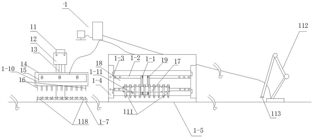
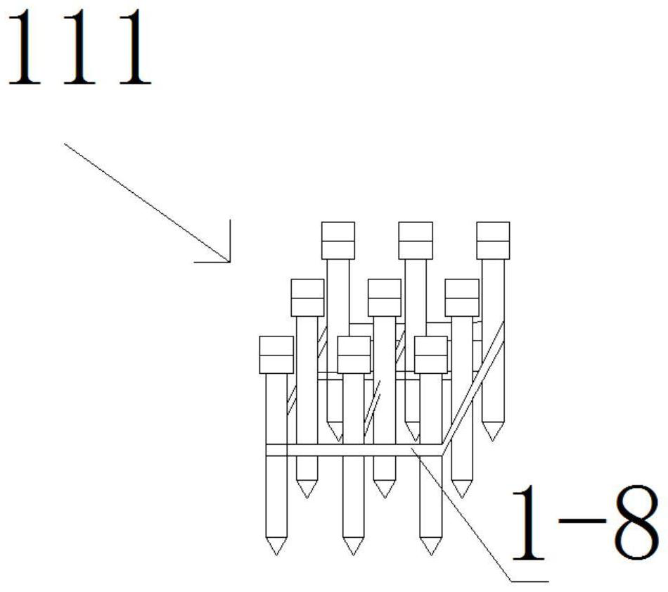
[0048] An automatic detection, automatic glue dispensing and automatic sorting device for LED lamp beads arranged in an array, including chip detection equipment for detecting whether each chip in the LED lamp beads 118 arranged in an array is working normally, Dispensing equipment for dispensing each chip in the LED lamp beads of the cloth, the dispensing equipment includes a plurality of dispensing machines 111 arranged in an array, and each dispensing machine 111 corresponds to an LED lamp bead that needs to be dispensed, so The chip detection device transmits the detection result of the working state of each chip in the LED lamp beads arranged in the array to the control system 1, and the control system 1 identifies the abnormally working chip and its corresponding coordinate information, and the system control and control are related to the control system 1. The electric valve 1-6 (see Fig. 1-D) of the glue dispenser corresponding to the chip coordinates is closed to stop ...
Embodiment 2
[0066] The chip detection equipment and detection substrate of Example 2 are different from those of Example 1. The positive level of each chip in the arrayed LED lamp beads of Example 2 is connected together to form a positive level (V1) detection terminal, The negative stage of each chip in the LED lamp beads arranged in the array is connected together to form a negative stage (V2) detection end, the positive stage (V1) detection end and the negative stage (V2) detection end The heads are preferably fixed adjacent to each other, and the relative positions of the positive level (V1) detection end and the negative level (V2) detection end can also be arbitrarily set, that is, each of the LED lamp beads arranged in the array The positive stage of the chip and the negative electrode of each chip are respectively connected in parallel. In this embodiment, the concept of parallel connection is realized by designing a suitable detection substrate.
[0067] see Figures 2A-2B , the...
Embodiment 3
[0073] The chip detection device of Embodiment 3 is different from that of Embodiment 1, and other aspects are the same as those of Embodiment 1.
[0074] like image 3 As shown, the chip detection device includes a column 3, the upper end of the column 3 is fixed with a first cylinder 31 that is electrically connected to the control system 1, and a first cylinder shaft 32 at the lower part of the first cylinder 31 stops the There is a first cover plate 33, the lower surface of the first cover plate 33 is provided with piezoelectric units arranged in an array corresponding to the LED lamp beads 312 arranged in the array, and each piezoelectric unit is used to give its corresponding Each piezoelectric unit specifically includes a piezoelectric layer 35 disposed on the lower surface of the first cover plate 33, and the lower ends of the piezoelectric layer 35 are respectively connected with a flexible conductive layer 36, The middle of the lower part of each piezoelectric layer...
PUM
 Abstract
Description
Claims
Application Information
 - R&D
- Intellectual Property
- Life Sciences
- Materials
- Tech Scout
- Unparalleled Data Quality
- Higher Quality Content
- 60% Fewer Hallucinations
Browse by: Latest US Patents, China's latest patents, Technical Efficacy Thesaurus, Application Domain, Technology Topic, Popular Technical Reports.
© 2025 PatSnap. All rights reserved.Legal|Privacy policy|Modern Slavery Act Transparency Statement|Sitemap|About US| Contact US: help@patsnap.com


