Control method and device of power switch device

A technology of a power switching device and a control method, which is applied to the output power conversion device, control drive, control system, etc., can solve the problems of large switching loss and low working efficiency of the motor controller, so as to improve efficiency, improve efficiency, and ensure The effect of safety and reliability

Pending Publication Date: 2022-07-29
CHINA FIRST AUTOMOBILE
View PDF0 Cites 0 Cited by
  • Summary
  • Abstract
  • Description
  • Claims
  • Application Information

AI Technical Summary

Problems solved by technology

[0004] The embodiment of the present invention provides a control method and device for a power switching device, so as to at least solve the technical problem in the related art that the working efficiency of the motor controller is low due to the large switching loss

Method used


Image

  • Control method and device of power switch device
  • Control method and device of power switch device
  • Control method and device of power switch device

Examples


Embodiment 1

[0035] According to an embodiment of the present invention, an embodiment of a method for controlling a power switching device is provided. It should be noted that the steps shown in the flowchart of the accompanying drawings can be executed in a computer system such as a set of computer-executable instructions, and , although a logical order is shown in the flowcharts, in some cases steps shown or described may be performed in an order different from that herein.

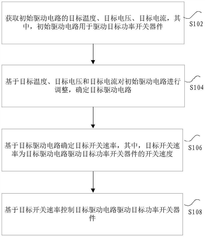
[0036] figure 1 It is a flow chart of a control method of a power switching device of a motor controller according to an embodiment of the present invention, such as figure 1 As shown, the method includes the following steps:

[0037]Step S102, acquiring the target temperature, target voltage, and target current of the initial driving circuit, wherein the initial driving circuit is used to drive the target power switching device.

[0038] The above-mentioned initial driving circuit may be a driving circuit of a p...

Embodiment 2

[0091] According to another aspect of the embodiments of the present invention, a control device for a power switching device is also provided, Figure 15 It is a schematic diagram of an apparatus for controlling a power switching device according to an embodiment of the present invention, such as Figure 15 As shown, the apparatus includes: an acquisition module 1502 for acquiring the target temperature, target voltage, and target current of the initial drive circuit, wherein the initial drive circuit is used to drive the target power switching device; the adjustment module 1504 is used for, based on the target temperature, The target voltage and the target current adjust the initial drive circuit to determine the target drive circuit; the determining module 1506 is configured to determine the target switching rate based on the target drive circuit, wherein the target switching rate is the switching speed at which the target drive circuit drives the target power switching devi...


PUM


Abstract

The invention discloses a control method and device of a power switch device. The method comprises the steps that the target temperature, the target voltage and the target current of an initial driving circuit are acquired, and the initial driving circuit is used for driving a target power switching device; adjusting the initial driving circuit based on the target temperature, the target voltage and the target current, and determining a target driving circuit; determining a target switching rate based on the target driving circuit, the target switching rate being a switching speed at which the target driving circuit drives the target power switching device; and controlling the target driving circuit to drive the target power switching device based on the target switching rate. According to the invention, the technical problem of low working efficiency of the motor controller caused by large switching loss in the prior art is solved.

Description

technical field [0001] The invention relates to the field of smart cars, and in particular, to a control method and device for a power switch device. Background technique [0002] At present, in order to ensure the reliable operation of the power switching device of the motor controller, the worst working conditions are generally selected for the adaptation of the drive parameters, that is, the final drive parameters must at least meet the working conditions of the highest voltage, the highest current, and the lowest temperature. Down. The driving parameters selected in this way make power switching devices, such as Insulated Gate Bipolar Transistor (IGBT collector voltage for short), always work at a slower switching rate, and the switching loss is large, especially at low speed. The low load area, therefore, leads to low working efficiency of the power switching device of the motor controller, which in turn leads to low efficiency of the motor system, which affects the ba...

Claims


Application Information

Patent Timeline
Patent Type & Authority Applications(China)
IPC IPC(8): H02M1/088H02P25/16B60L15/00
CPCH02M1/088H02P25/16B60L15/00
Inventor 钟华刘志强赵慧超王斯博王宇文彦东
Owner CHINA FIRST AUTOMOBILE
Why Eureka
Try Eureka