Built-in heat dissipation fan structure for cascade type power electronic device

A technology of power electronic devices and heat dissipation fans, which is applied in the cooling/ventilation of substation/switchgear, substation/distribution device shell, substation/switch arrangement details, etc. Or problems such as large container volume and large overall size of the device cabinet, to achieve the effect of improving power density and space utilization, neat and generous appearance, and effective and reasonable noise

Pending Publication Date: 2022-07-29
SHANGHAI ELECTRICGROUP CORP +1
View PDF0 Cites 0 Cited by
  • Summary
  • Abstract
  • Description
  • Claims
  • Application Information

AI Technical Summary

Problems solved by technology

Regardless of the position of the cooling air duct on the top or the back of the device, the heat dissipation fan and the cooling air duct are all external structural designs. From the style point of view, they are all convex or backpack design schemes, resulting in the overall cabinet of the device. The size is too large, occupying the power distribution room or the volume of the container becomes larger, and the price cost is greatly increased
This convex hull or backpack design not only affects the overall lifting or transportation safety of the device cabinet, but also affects the overall appearance of the product

Method used


Image

  • Built-in heat dissipation fan structure for cascade type power electronic device
  • Built-in heat dissipation fan structure for cascade type power electronic device
  • Built-in heat dissipation fan structure for cascade type power electronic device

Examples


Embodiment Construction

[0024] The present invention will be further described below with reference to the accompanying drawings and embodiments.

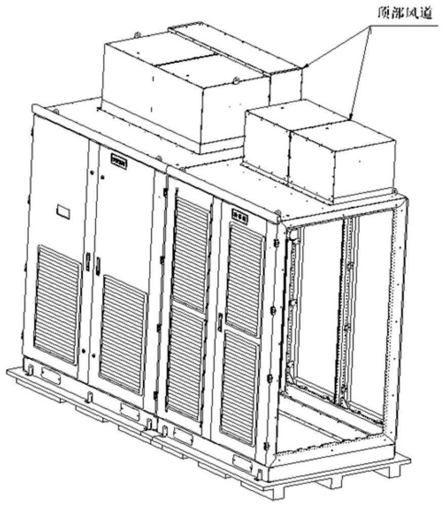
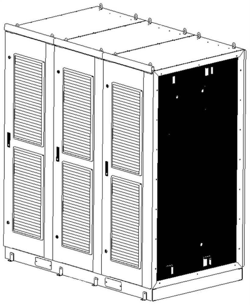
[0025] like Figure 2 to Figure 9 As shown in the figure, a built-in cooling fan structure for a cascaded power electronic device includes a built-in fan cabinet 1 of the cascaded power electronic device, a rear door panel 2 of the cascaded power electronic device cabinet, and a cascaded power electronic device. The honeycomb air outlet on the rear door panel of the electronic device 3, the cooling fan installation cover 4, the cooling fan 5, the cooling fan wind guide ring 6, the cooling air duct 7, the cooling air duct rear panel 8, the cooling air duct upper panel 9, Fastening bolt holes 10.

[0026] The inside of the built-in fan cabinet 1 of the cascaded power electronic device is provided with a plurality of cooling air cavities, the top of each cooling air cavity is provided with a cooling fan 5, and the rear is provided with a cooling air duct re...


PUM


Abstract

The invention relates to a built-in heat dissipation fan structure for a cascade type power electronic device, which comprises a built-in fan cabinet body of the cascade type power electronic device, a plurality of heat dissipation air cavities are arranged in the built-in fan cabinet body of the cascade type power electronic device, a heat dissipation fan device is arranged at the top of each heat dissipation air cavity, and a heat dissipation air channel is arranged at the back of each heat dissipation air cavity. A rear door plate of the built-in fan cabinet body is provided with honeycomb air outlet holes, the heat dissipation fan device sucks air from a window behind the cascade type power electronic device, the air enters a concentrated heat dissipation air cavity through a radiator of a power unit, and then the air is exhausted from the honeycomb air outlet holes in the rear door plate of the built-in fan cabinet body, so that a complete heat dissipation air channel is formed. According to the structure, the internal space of the device cabinet body can be reasonably utilized, a series of problems and defects caused by a convex hull type or backpack type external heat dissipation air channel are perfectly solved, and the internal space utilization rate of the device cabinet body and the power density of the whole device are greatly improved.

Description

technical field [0001] The invention relates to a built-in fan installation method for cascaded power electronic devices, in particular to a structure of a built-in cooling fan. Background technique [0002] At present, for each cascaded power electronic device, there are two ways to design the air-cooling and heat-dissipating air duct: one is to install it on the top of the device, which increases the height of the device; figure 1 shown, the other is mounted on the back of the unit, increasing the depth of the unit. The external air duct is generally a convex hull design in the height direction (2200mm) of the power cabinet or a backpack design in the depth direction (1200mm). Regardless of the location of the cooling air duct on the top of the device or the back of the device, the cooling fan and the cooling air duct are externally designed. From the style point of view, they are all convex hull or backpack-type designs, resulting in the overall design of the device cabi...

Claims


Application Information

Patent Timeline
IPC IPC(8): H02B1/56H02B1/30H02B1/32
CPCH02B1/565H02B1/30H02B1/306H02B1/32
Inventor 陈国栋王江涛邢新波沈金华王磊周鸿飞刘超
Owner SHANGHAI ELECTRICGROUP CORP
Why Eureka
Try Eureka