


Quick Research
Generate reliable direction feasibility study reports for your R&D in just a few steps.

Technical Q&A
Discover and master advanced knowledge NOW. Basics, ideas, possibilities, all at once.

Find Solutions
As an expert in R&D theories, this can generate solutions to your technical problems instantly.

Evaluate Feasibility
Analyze your overall solution with one click, know your potential R&D risks in advance.

Monitor Landscape
Get weekly tech updates, stay abreast of the latest tech innovations and key insights.
Air valve
A technology of air valves and vents, applied in the field of electric air valves, can solve the problems of weak deformation resistance, poor mechanical strength, and poor sealing performance of the valve plate, and achieve strong deformation resistance, high structural mechanical strength, and low air leakage rate Effect
- Summary
- Abstract
- Description
- Claims
- Application Information
AI Technical Summary
Problems solved by technology
Method used
Image

Examples
Embodiment 1
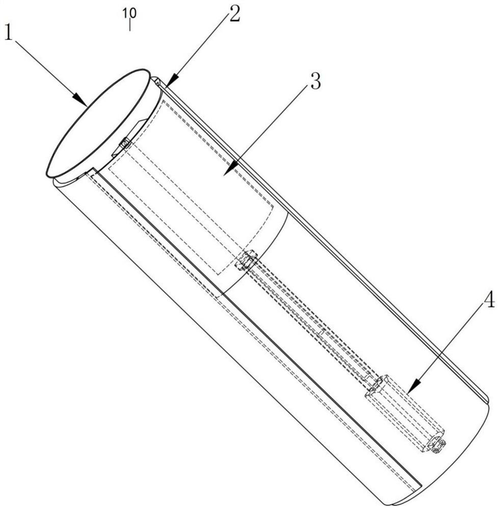
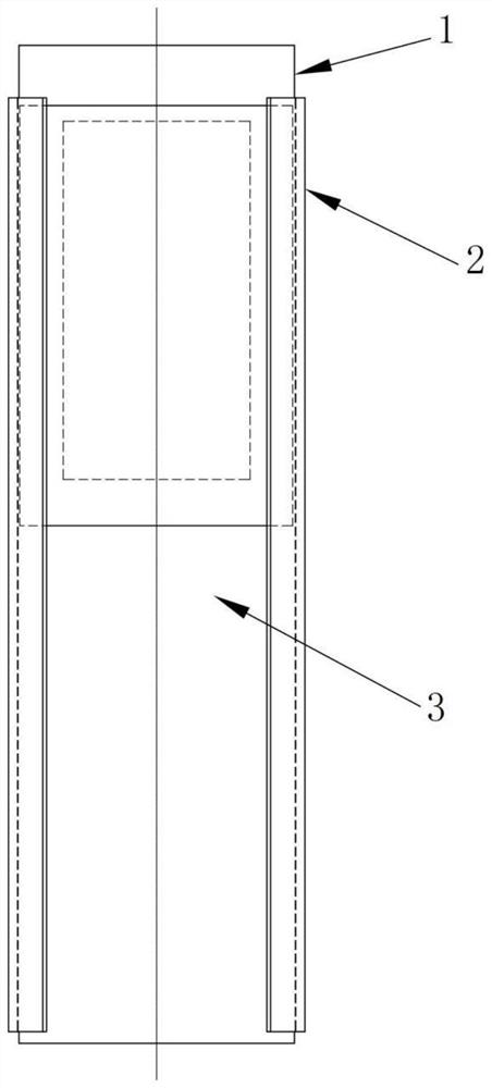
[0033] Please refer to Figure 2 to Figure 4 , This embodiment provides an air valve 10, which is suitable for a circular air duct. The air valve 10 includes a cylindrical tube with an interlayer and a circular arc slide 3. One end of the cylindrical tube is open. When in use, the open end is connected to the circular air duct, so that the inner channel of the cylindrical tube is connected to the circular air duct. Air ducts are connected. The other end of the cylindrical tube is sealed. A vent is provided on the side wall of the cylindrical tube. The circular arc sliding piece 3 is arranged on the interlayer of the cylindrical tube, and the circular arc sliding piece 3 can close or open the ventilation opening under the driving of the driving device 4 .
[0034] In this embodiment, the output of the driving device 4 is linear motion, that is, the arc sliding vane 3 is driven by the driving device 4 to perform linear motion.
[0035] The cylindrical tube includes an inner ...
Embodiment 2
[0044]This embodiment is further improved on the basis of Embodiment 1. In this embodiment, the cylindrical tube of the air valve 10 in Embodiment 1 is improved, and other structures are the same as those of Embodiment 1. In this example, both ends of the cylindrical tube in Example 1 are set to be open, that is, both ends of the inner cylindrical sleeve 1 of the cylindrical tube in Example 1 are set to be open. When the air valve 10' of this embodiment is used, it is necessary to connect the two ends of the cylindrical pipe of the air valve 10' to the port of a circular air pipe respectively. Please refer to Figure 7 , for example, the air valve 10' described in Embodiment 2 is provided between the circular air duct 1 20 and the circular air duct 2 30, and the air valve described in Embodiment 1 is provided at the end of the circular air duct 2 30 10.
Embodiment 3
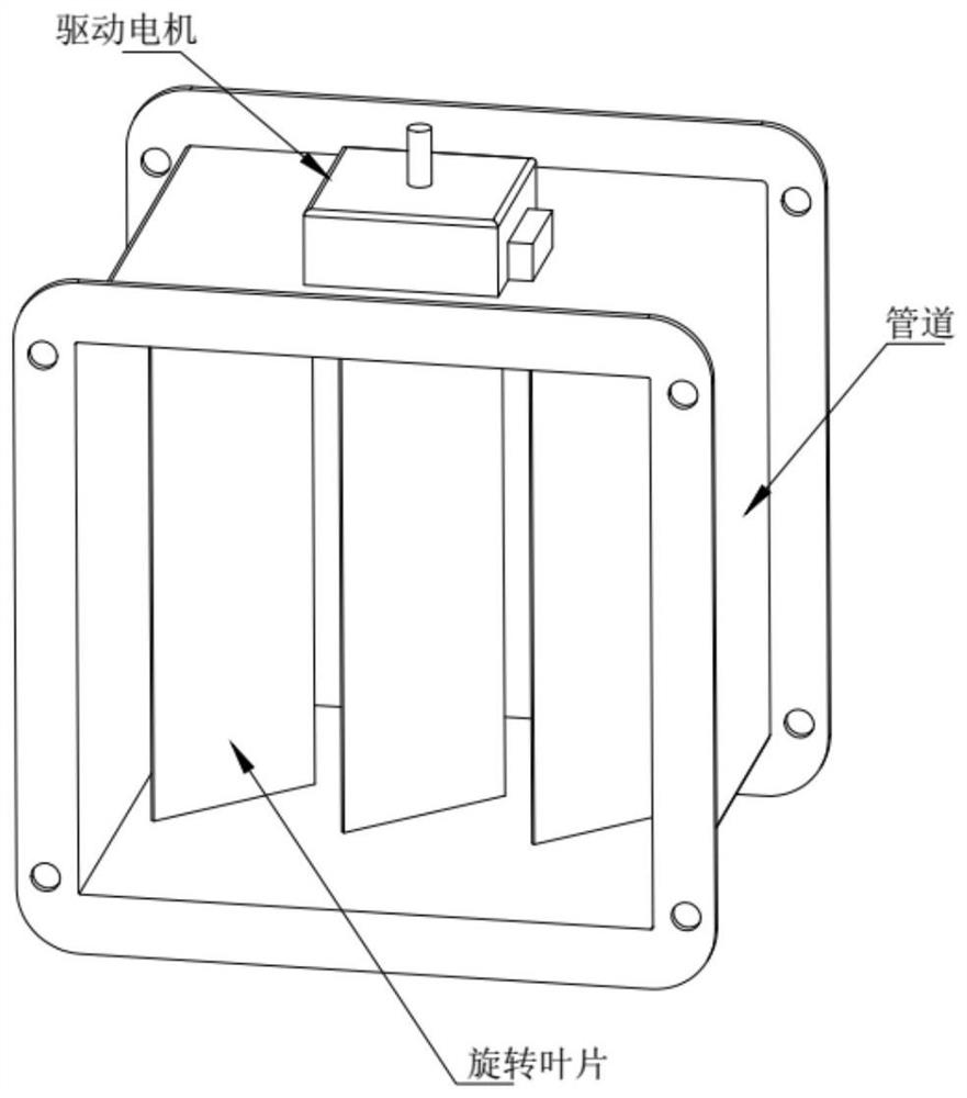
[0046] This embodiment is further improved on the basis of Embodiment 1 and Embodiment 2. In this embodiment, please refer to Figure 8 , the drive motor is arranged on the outside of the cylindrical tube, the purpose is to facilitate the maintenance of the drive motor.
PUM
 Abstract
Description
Claims
Application Information
 - R&D Engineer
- R&D Manager
- IP Professional
- Industry Leading Data Capabilities
- Powerful AI technology
- Patent DNA Extraction
Browse by: Latest US Patents, China's latest patents, Technical Efficacy Thesaurus, Application Domain, Technology Topic, Popular Technical Reports.
© 2024 PatSnap. All rights reserved.Legal|Privacy policy|Modern Slavery Act Transparency Statement|Sitemap|About US| Contact US: help@patsnap.com