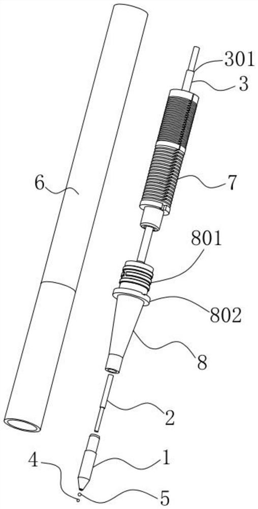
Pressing direct liquid type double-ball refill
A direct liquid type, refill technology, used in ballpoint pens, printing, writing utensils, etc., can solve the problems of non-smooth writing due to the friction between the ball and the water core, the volatile and drying ink, and the incompatibility of writing pens, etc. Product stability, uniform ink output, and the effect of preventing ink leakage
- Summary
- Abstract
- Description
- Claims
- Application Information
AI Technical Summary
Problems solved by technology
Method used
Image
Examples
Embodiment 2
[0053] The difference between this embodiment and the first embodiment is that the limiting structure between the water storage 7 and the second water guiding core 3 is different. Specifically, see Image 6 , in this embodiment, the upper end of the water reservoir 7 extends toward the ink storage chamber 601 to form a top plate 703 facing the insertion hole 701, wherein the connection portion between the top plate 703 and the upper end of the water reservoir 7 is provided for ink The upper end face of the second water diversion core 3 abuts on the top plate 703, thereby realizing the limit of the second water diversion core 3 by the water storage 7. This structural design reduces the need for secondary water diversion cores 3. The process of processing the second limit step 301 improves the production efficiency of the product.
Embodiment 3
[0055] The difference between this embodiment and the first embodiment is that the limiting structure between the water storage 7 and the second water guiding core 3 is different. Specifically, see Figure 7 , in this embodiment, the second water diversion core 3 and the water reservoir 7 are limited by interference fit. By increasing the amount of interference and the length of the interference between the upper part of the jack 701 and the second water diversion core 3, the distance between them is increased. The friction force between the second water diversion core 3 and the upper part of the water storage tank 7 is realized. This structural design does not need to set the first limit step 702 on the water storage tank 7, and also reduces the need for the second water diversion core 3. The second step of processing the second limit step 301 improves the production efficiency of the product.
Embodiment 4
[0057] The difference between this embodiment and the first embodiment or the second embodiment or the third embodiment is that the shape of the pen tip 1 is different. Figure 8 Shown is a cross-sectional view of the fourth embodiment using a needle tip. The pen tip 1 is provided with a plurality of limit bumps 105 distributed in an annular shape in the ink flow channel 101 near the bowl mouth 102 of the tip. The upper part is jointly constructed to form a ball seat part 103 , and the lower ink groove 104 is formed by the gap between two adjacent limiting bumps 105 . In order to match the needle tube tip, the diameter of the first water guiding core 2 is correspondingly set to be smaller than the inner diameter of the needle tube tip, so that the two ends of the first water guiding core 2 can abut on the second water guiding core 3 and the second ball respectively. 5, to achieve the normal function of guiding ink.
PUM
 Abstract
Description
Claims
Application Information
 - Generate Ideas
- Intellectual Property
- Life Sciences
- Materials
- Tech Scout
- Unparalleled Data Quality
- Higher Quality Content
- 60% Fewer Hallucinations
Browse by: Latest US Patents, China's latest patents, Technical Efficacy Thesaurus, Application Domain, Technology Topic, Popular Technical Reports.
© 2025 PatSnap. All rights reserved.Legal|Privacy policy|Modern Slavery Act Transparency Statement|Sitemap|About US| Contact US: help@patsnap.com


