Method and corollary equipment for cutting NOL ring test sample strip by water jet
A kind of supporting equipment, water jet technology, applied in sampling device, metal processing and other directions, can solve the problems of back and forth movement, complex cutting process, unfavorable batch sample cutting, etc., to achieve convenient cutting, simple operation process, and eliminate hidden dangers of cutting safety Effect
- Summary
- Abstract
- Description
- Claims
- Application Information
AI Technical Summary
Problems solved by technology
Method used
Image
Examples
Embodiment 1
[0032] This embodiment relates to a supporting device for cutting NOL ring test strips by water jet.
[0033] The present embodiment relates to a water jet cutting matching device for NOL ring test strips, and specifically relates to a matching device for cutting NOL ring test strips by using the water jet cutting method.
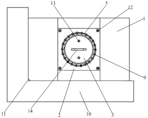
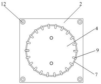
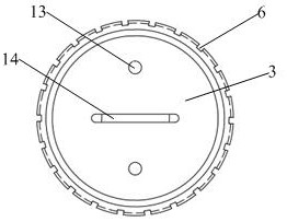
[0034] like figure 1 As shown, the supporting equipment is mainly composed of a base bottom plate 1 , a lower snap ring 2 , an upper snap ring 3 and a positioning plate 10 . Lower snap ring 2 such as figure 2 As shown in the structure, it is a plate-like structure on which a number of arc-shaped protrusions 7 are arranged, and a plurality of arc-shaped protrusions 7 are enclosed to form a circular groove body 4, and the gap between each adjacent arc-shaped protrusions 7 is In order to facilitate cutting by the water jet, a cutting groove 9 is also provided on the lower snap ring 2 below the cutout 6 . Upper snap ring 3 such as image 3 , Figure 4 As ...
Embodiment 2
[0039] This embodiment relates to a method for cutting NOL ring test strips by water jet. Using the supporting equipment described in Example 1, the cutting steps are as follows:
[0040] S1: Place the positioning plate 10 in the cutting water tank, and design the two adjacent sides on the base plate 1 to eliminate the corners, so that the position of the chamfer is placed close to the cutting origin 11 of the positioning plate 10, and ensure the design of the base plate 1 The two side edges of the chamfer are abutted against the two right-angle edges of the positioning plate 10 .
[0041] S2: Put the NOL ring to be cut into the groove body 4, then hold the handle 14 and put the upper snap ring 3 into the groove body 4, so that the NOL ring is inserted into the cavity 5 formed by the groove body 4 and the upper snap ring 3 , the upper snap ring 3 is positioned and assembled in the groove body 4 through the positioning pin 13 .
[0042] S3: Turn on the water jet cutting equipme...
PUM
 Abstract
Description
Claims
Application Information
 - R&D
- Intellectual Property
- Life Sciences
- Materials
- Tech Scout
- Unparalleled Data Quality
- Higher Quality Content
- 60% Fewer Hallucinations
Browse by: Latest US Patents, China's latest patents, Technical Efficacy Thesaurus, Application Domain, Technology Topic, Popular Technical Reports.
© 2025 PatSnap. All rights reserved.Legal|Privacy policy|Modern Slavery Act Transparency Statement|Sitemap|About US| Contact US: help@patsnap.com


