
Industrial robot connecting base with angle convenient to adjust and using method of industrial robot connecting base

An industrial robot and angle adjustment technology, applied in the field of robotics, can solve problems such as robot operating angle and radius restrictions, and achieve the effect of improving stability

Pending Publication Date: 2022-07-29
徐立永
View PDF0 Cites 0 Cited by
  • Summary
  • Abstract
  • Description
  • Claims
  • Application Information

AI Technical Summary

Problems solved by technology

[0003] It is found in the use of the existing industrial robot connection base that it can only be fixed but cannot be tilted at an angle, which limits the working angle and radius of the robot;
[0004] In some existing patent solutions, the tilt angle adjustment of the platform is realized by setting a swing mechanism. For example, multiple telescopic rods are used to change the tilt angle by virtue of different telescopic degrees. However, since the tops of the telescopic rods are generally connected by hinges Adjustment plate, so that after the target angle is reached, it also needs to be locked by means of a locking mechanism, so a separate locking mechanism is also required

Method used


Image

  • Industrial robot connecting base with angle convenient to adjust and using method of industrial robot connecting base
  • Industrial robot connecting base with angle convenient to adjust and using method of industrial robot connecting base
  • Industrial robot connecting base with angle convenient to adjust and using method of industrial robot connecting base

Examples


Embodiment

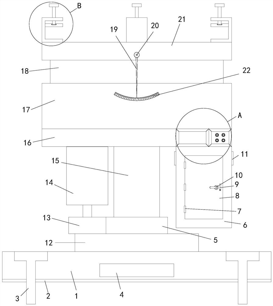
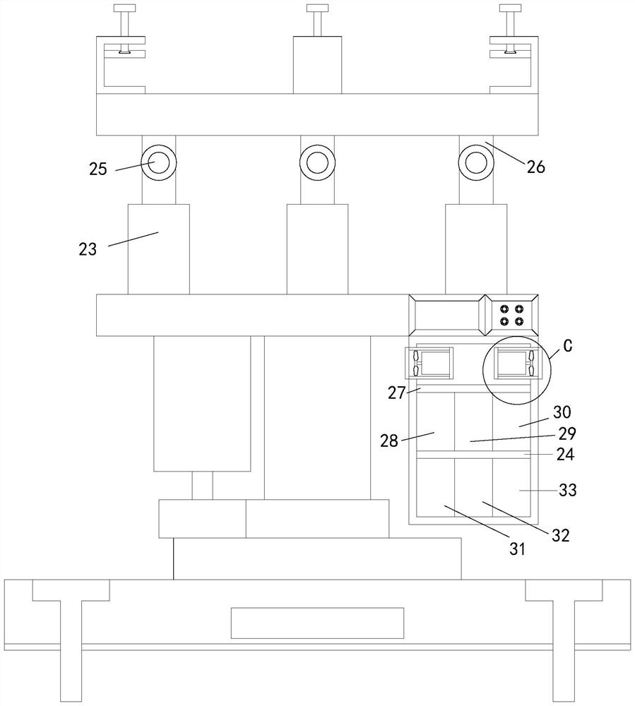
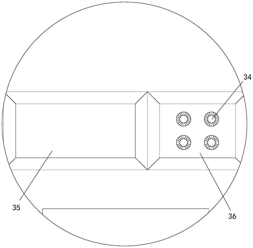
[0033] see Figure 1-5 , an industrial robot connection base that is easy to adjust the angle, including a chassis 1, the top of the chassis 1 is provided with a rotating shaft 12, and the circumferential inner wall of the rotating shaft 12 is sleeved with a shaft 15, and the circumferential outer wall of the shaft 15 is sleeved with a gear 5 , and the top end of the shaft rod 15 is provided with a connecting plate 16, the bottom end of the connecting plate 16 is provided with a motor one 14, and the output end of the motor one 14 is provided with a gear two 13, the gear one 5 and the gear two 13 are meshed and connected. The bottom end of the board 16 is provided with the control cabinet 6, and the front end of the control cabinet 6 is provided with a first square hole, the front end of the first square hole is covered with a shutter 8 through a set of hinges 7, and the front end of the connecting plate 16 is provided with a display. The screen 35 is provided with a control b...


PUM


Abstract

The invention relates to the technical field of robots, in particular to an industrial robot connecting base facilitating angle adjustment and a using method thereof.The industrial robot connecting base comprises a chassis, a first rotating shaft is arranged at the top end of the chassis, a shaft rod sleeves the circumferential inner wall of the first rotating shaft, a first gear sleeves the circumferential outer wall of the shaft rod, and a connecting plate is arranged at the top end of the first shaft rod; a first motor is arranged at the bottom end of the connecting plate, a control cabinet is arranged at the bottom end of the connecting plate, a first square hole is formed in the front end of the control cabinet, telescopic rods are arranged at the four corners of the top end of the connecting plate, the bottom end of each screw rod penetrates through the corresponding clamping claw and extends into the corresponding clamping claw, and a second rotating shaft is arranged at the bottom end of each screw rod. And a pressing plate is arranged in each clamping claw, and a first connecting plate and a second connecting plate are connected between the left side wall and the right side wall of the control cabinet, so that angle inclination can be achieved, the operation angle and radius are increased, and the practicability is high.

Description

technical field [0001] The invention relates to the technical field of robots, in particular to an industrial robot connecting base which is convenient for angle adjustment and a method of using the same. Background technique [0002] As we all know, industrial robots are multi-joint manipulators or multi-degree-of-freedom mechanical devices widely used in the industrial field. They have a certain degree of automation and can realize various industrial processing and manufacturing functions by relying on their own power energy and control capabilities. Industrial robots are widely used. In various industrial fields such as electronics, logistics, chemical industry, etc. [0003] The existing industrial robot connection base is found in use, which can only be fixed and cannot be tilted at an angle, which limits the working angle and radius of the robot; [0004] In some of the existing patent solutions, the tilt angle adjustment of the platform is realized by setting a swing...

Claims


Application Information

Patent Timeline
Patent Type & Authority Applications(China)
IPC IPC(8): B25J19/00
CPCB25J19/00
Inventor 徐立永
Owner 徐立永
Learn More